Triangular LED surfaces · plan the corners, edges and image map
Triangle LED Display
Triangle LED Display is a flat three-sided LED surface or a repeated triangular arrangement. Its appeal comes from a clear geometric outline, but the corners and diagonal pixel edges affect both construction and content. Define the side lengths, corner geometry, orientation and whether the project uses a single triangle or repeated units before selecting the panel layout.
Send Drawing & Dimensions →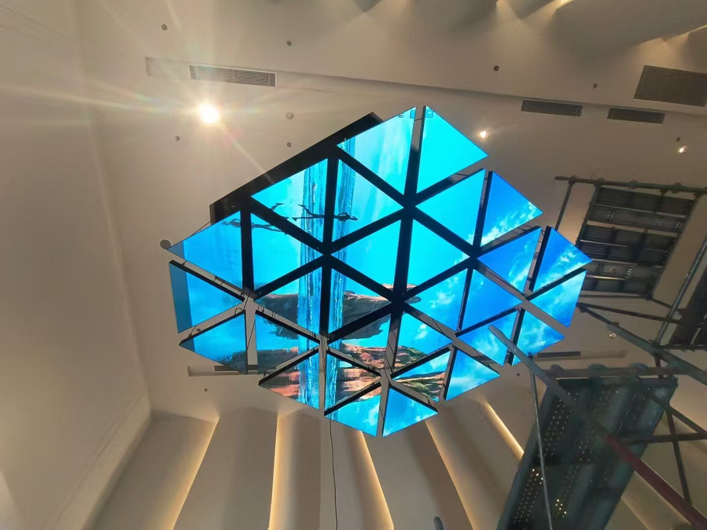
Definition
Fix the Triangle Geometry Before Planning the Pixel Layout
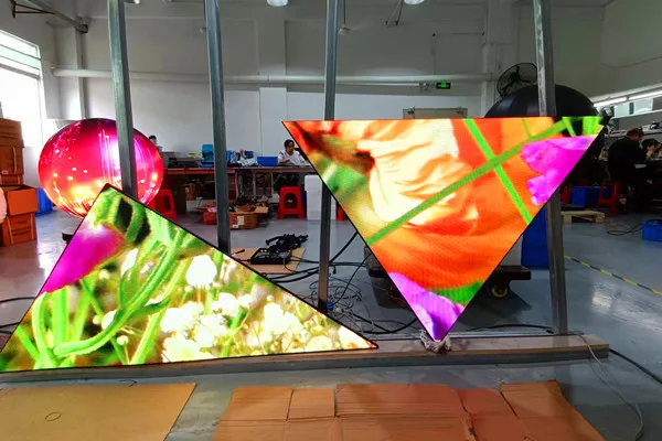
Start with the intended shape: equal-sided, asymmetric or part of a larger tiled composition. Record the three sides and corners on an elevation, then mark which faces emit light and how the triangle is oriented at installation. This prevents an attractive concept image from leaving the corner joints, edge cuts or mounting points open to interpretation.
A repeatable six-sided cell belongs under Hexagon LED Screen. If the outline is not a defined triangle or standard polygon, use Custom LED Display to scope a made-to-drawing design.
Engineering
Engineering the Geometry of Triangle LED Display
Three side lengths
Dimension each side independently unless the design explicitly specifies equal lengths. The side schedule controls the finished outline and helps identify whether panels or support sections repeat.
Three corner angles
Confirm the included corner angles and how they relate to the side dimensions. These values affect corner closure, the frame and alignment between adjoining triangular units.
Triangle orientation
Show the installed orientation—apex up, down or toward a fixed site datum. Orientation changes the content canvas and the way multiple triangles align.
Edge segmentation
Define how panel rows or cabinet segments meet the sloping sides. Include corner treatment and any non-display edge so the fabricator knows what forms the visible perimeter.
Usable pixel boundary
Map the real illuminated pixels, including any stepped or clipped rows near the diagonal boundary. This is the usable canvas for artwork and controller configuration.
Tiling gap between triangles
For a field of triangles, set the intended gap or seam between units and give a datum for each cell. Consistent spacing makes the pattern read as designed and simplifies installation.
Specification
Drawing Inputs for a Triangle LED Display
| Shape-specific engineering parameter | Value | Engineering use |
|---|---|---|
| Three side dimensions | Project-defined / confirm by drawing | Defines the outer triangle and whether the sides are equal, paired or all different. |
| Corner angles | Project-defined / confirm by drawing | Confirms the corner closure and the shape of the support frame. |
| Installed orientation and datum | Project-defined / confirm by drawing | Sets apex direction and repeatable alignment for tiling or mounting. |
| Panel segmentation at diagonal edges | Project-defined / confirm by drawing | Shows how modules or cabinets form the sloping sides and corners. |
| Active pixel boundary | Project-defined / confirm by drawing | Identifies illuminated rows and inactive margins for the controller map. |
| Unit spacing and repeated quantity | Project-defined / confirm by drawing | Coordinates visual rhythm, mounting positions and the installation pattern. |
These are project inputs for quoting and engineering, not fixed Highcolor product specifications. Confirm pitch, brightness, protection, module construction and electrical requirements for the selected LED platform and installation conditions.
Content & mapping
Map Content to the Triangle’s Usable Pixel Area
A rectangular source file does not mean every pixel fits inside a triangular face. Define the controller canvas from the actual active rows and diagonal boundary, including any inactive corners or gaps between repeated units.
Place logos and text with the triangle’s orientation in mind; an apex can leave little room for words near the tip. Preview the artwork with a pixel grid and test pattern to catch clipped edges, uneven margins and mismatched seams before content is finalized.
Installation decision
Design the Frame and Tiling Pattern Together
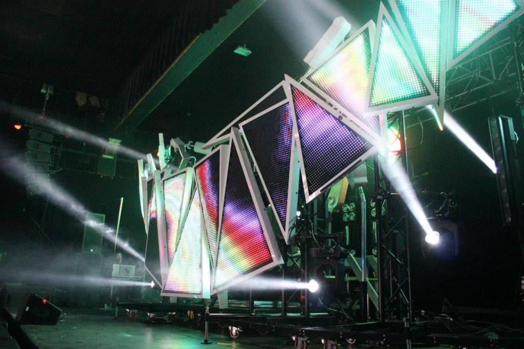
The support must hold each triangle at the specified angle and keep the visible edges aligned. For a multi-unit installation, establish a master datum, unit spacing, fastening locations and cable routes before fabrication. Confirm access to modules and connections from the chosen front or rear service side, particularly when triangles are installed overhead or integrated into a stage structure.
For repeating six-sided geometry, compare Hexagon LED Screen; for a unique outline or complex transition, see Custom LED Display.
Cost drivers
What Affects the Cost of a Triangle LED Display?
The main cost variables are the triangle’s area and pixel density, how its sloped edges are built, whether the same unit repeats, and the support and finish needed at the corners. Content mapping and on-site alignment also matter when several triangles must read as one composition. A dimensioned drawing is needed for a meaningful quote.
Triangle Size
Larger faces need more active area and support. Side proportions also affect the count and arrangement of panel sections.
Edge Segmentation
The diagonal boundary may require stepped module rows, custom edges or a visible trim solution. Show the preferred edge finish.
Number Of Repeated Units
Repeated identical triangles can share a layout; mixed sizes and orientations require separate part, support and mapping details.
Content Clipping At Diagonal Edges
The controller map must define clipped pixels at each sloping side. Complex content alignment across tiled triangles can add commissioning and content-preparation work.
Drawing review
Review the Triangle Drawing Before Fabrication
Before release, verify that the drawing describes both the physical triangle and its pixel canvas. For repeated units, check the master orientation and spacing; for a single face, check corner closure, diagonal edges and mounting. The following items prevent geometry and content assumptions from diverging.
Three side dimensions
Check all three measured sides against the intended equal or unequal triangle. Confirm whether the dimensions refer to the illuminated face, trim or outside frame.
Corner angles
Confirm that the three corners close to the intended outline and that the support details follow those angles. Flag any rounded, clipped or non-standard corner.
Triangle orientation
Mark the apex direction and a fixed datum on the drawing. Match that orientation in the assembly plan, content preview and controller map.
Edge segmentation
Review the module or cabinet boundaries along every sloping edge. Specify corner cuts, trim and the acceptable visible seam at panel joins.
Usable pixel boundary
Compare the active pixel grid with the mechanical outline. Identify clipped rows, inactive corner pixels and margins so artwork is mapped only to the real LED area.
Tiling gap between triangles
For multiple units, dimension the spacing and locate each triangle from a shared datum. Confirm that the gap remains consistent after mounting and content alignment.
FAQ
Triangle LED Display Engineering FAQ
Can a Triangle LED Display use three unequal sides?
That depends on the chosen cabinet or module layout and the fabrication plan. Send all three side dimensions and corner angles; do not assume an equilateral shape unless the drawing explicitly calls for equal sides.
How do I prepare content for a triangular screen?
Use the approved pixel map rather than cropping a rectangular video by eye. Protect key text and logos from the narrow apex and diagonal edges, and preview the final artwork against the actual active pixel rows.
Can multiple triangular screens be tiled together?
Yes, if the project defines each triangle’s size, orientation, spacing and common datum. Confirm how seams and gaps appear in the content and coordinate the physical layout with the controller mapping.
What information is needed for an accurate quotation?
Provide side dimensions, corner angles, orientation, active pixel boundary, number of units, spacing, viewing distance, indoor or outdoor environment and mounting details. Drawings should distinguish the active LED face from frame and trim.
What should be checked before a triangular display is installed?
Verify corner closure, diagonal-edge finish, mounting datum, unit spacing, service access and the controller test pattern. For tiled compositions, check alignment across all triangles before the final content is commissioned.
Internal selection links
Compare Shapes With Different Engineering Intent
A six-sided repeating geometry suited to honeycomb or tiled layouts; its cell alignment and shared edges differ from a three-corner triangle.
A made-to-drawing route for outlines, transitions or installation interfaces that do not fit a standard named geometry.
A surface designed around a 90-degree turn, where the corner and viewing planes—not a flat three-sided outline—drive the engineering.
Request a Triangle LED Display Review
Send the side dimensions, corner angles, installed orientation, active pixel boundary, unit spacing, viewing distance and mounting details so the geometry and controller map can be reviewed together.
Request Engineering Review →