CUSTOM-SHAPE LED SYSTEMS · PROJECT ENGINEERING
Creative LED Display
Creative LED displays combine custom geometry, pixel layout, support structure and content mapping in one engineered system. They suit retail landmarks, museums, exhibitions, branded spaces and architecture where a standard flat rectangle does not fit the concept.
Send Drawing & Dimensions →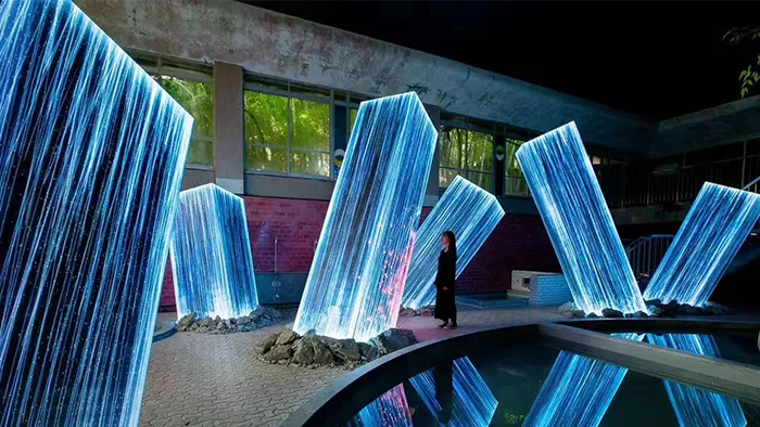
Creative LED display installation example
Use this image as a visual reference; confirm the actual form, active faces and dimensions from the project drawings.
Definition
What makes a creative LED display different?
The screen shape affects more than appearance: it changes module segmentation, structural support, pixel mapping, installation sequence and maintenance access. Start by identifying whether the design is curved, faceted, multi-face or another custom form, then test that geometry against real viewing positions and site constraints.
This overview helps compare creative LED display design routes and identify feasibility inputs. Once the form is clear, use the matching shape-specific page and a controlled drawing to confirm the build.

Curved LED display example
A curved screen is one design route; confirm the required radius, active surfaces and transitions against the approved drawing.
Engineering
Geometry and installation inputs that drive the design
Overall envelope (W × H × D)
Set the maximum width, height and depth, including edge clearances, installation tolerance and any architectural surfaces the display must align with.
Active LED surface definition
Mark which faces contain pixels and which are inactive, such as seams, cut-outs, caps, trim or hidden return surfaces. This defines the true image area.
Primary viewing-distance range
Record nearest, typical and farthest audience positions and their viewing angles. Use these conditions to compare pixel-pitch options and test legibility.
Geometry / CAD reference
Provide dimensioned elevations, sections and a 3D/CAD reference tied to measured site conditions and clear installation datums.
Module segmentation strategy
Show module or cabinet boundaries, curved or faceted transitions, joint locations and any limits on segment size. Confirm feasibility with the selected display platform.
Service-access direction
Mark front or rear access, removal clearances and the path to modules, power supplies and control components after cladding and adjacent finishes are installed.
Specification
Creative LED display RFQ drawing checklist
| RFQ input | Value | Why it matters |
|---|---|---|
| Overall envelope (W × H × D) | Project-defined / confirm by drawing | Defines the physical boundary, depth and clearances for support and installation. |
| Active LED surface definition | Project-defined / confirm by drawing | Identifies the real pixel-bearing area and surfaces that must stay inactive. |
| Primary viewing-distance range | Project-defined / confirm by drawing | Guides pixel-pitch selection and content legibility checks from the actual audience positions. |
| Geometry / CAD reference | Project-defined / confirm by drawing | Coordinates site measurements, structure, attachment points and fabrication references. |
| Module segmentation strategy | Project-defined / confirm by drawing | Makes seams, assembly order and repeatable module/cabinet sections reviewable. |
| Service-access direction | Project-defined / confirm by drawing | Keeps components reachable for inspection, repair and future replacement. |
These are project-specific engineering inputs, not fixed Highcolor product specifications. Confirm dimensions, pixel pitch, brightness, protection and construction for the selected display platform.
Content & mapping
Map the pixel canvas to the physical LED surfaces
The content canvas and controller map should follow the actual active pixels, not an assumed rectangle. Mark each active face, orientation and coordinate origin, then identify seams, openings, occlusions and inactive zones before content is produced.
For a wrapped, split or multi-face display, test representative motion and text from the intended viewing positions. Confirm how content crosses edges and where it should stop before the pixel map is released.
Pixel-map planning view
The project controller map should identify active faces, pixel coordinates, seams and inactive zones before media is produced.
Installation decision
Coordinate the support structure and service route
Keep the display geometry and its supporting structure as separate engineered items. Agree on installation datums, attachment points, segment joints, installation order, cable routes and service clearances with the project’s qualified structural and installation team.
Confirm the structure against site conditions and applicable load requirements before fabrication. Do not rely on LED modules to absorb errors in an unsupported or uneven frame; preserve a practical removal path for replaceable parts.
Cost drivers
What drives the cost of a custom-shape LED display?
A useful budget compares the LED system and the custom work around it. Request separate scope for display hardware, support structure, content mapping, installation and shipping so design changes are visible in the estimate.
Geometry and segment count
More unique surfaces, transitions and assembly sections increase drawing, alignment and fabrication effort.
Active area and pixel pitch
These determine the LED quantity and resolution; closer viewing generally calls for a finer-pitch review.
Support structure and access
Custom frames, site constraints, lifting and service access can add material and installation scope.
Control and content mapping
Irregular pixel layouts may need additional controller planning, commissioning and content adaptation.
Drawing review
A practical drawing review before production
Review the design in stages: concept fit, engineering release and preproduction approval. For each controlled revision, check these items against the site and display platform so geometry, structure, pixels and maintenance remain aligned.
Dimensioned envelope and tolerances
Check width, height, depth, edge clearances, mounting datums and transition dimensions against measured site conditions. Record the approved tolerances and drawing revision.
Pixel-bearing faces and exclusions
Identify active LED faces and mark every seam, cut-out, cap, trim or non-display surface. Reconcile the mechanical drawing with the controller pixel map and content canvas.
Viewing positions and sample content
Review nearest and typical audience positions, viewing angles and ambient conditions. Test representative text and motion before confirming pixel pitch and content layout.
CAD, site survey and installation datums
Keep the fabrication model, dimensioned elevations and site survey on the same revision. Resolve any mismatch in structure, attachment points or neighboring finishes before release.
Segments, joints and control zones
Confirm module or cabinet boundaries, seam positions, power and data routes, controller zones and installation sequence. Check that the intended segments can be transported and assembled at the site.
Service and replacement access
Verify that technicians can isolate power and reach replaceable modules and internal components after cladding is complete. Include removal clearance, tools and safe working access in the approved design.
FAQ
Custom-shape LED display planning FAQ
What information should I send for a custom-shape LED display quote?
Provide a dimensioned sketch or CAD model, overall width, height and depth, active LED faces, intended viewing positions, installation environment, mounting concept, service access and the content or pixel-map goal. A concept rendering is useful, but it does not replace dimensions and site conditions.
Can a creative LED display use standard 16:9 content?
Some installations use a rectangular canvas, but curved, split or multi-face designs may not. Define the real active pixel map and coordinate origin with the display and content teams, then test the intended media format before production.
How do I choose pixel pitch for a custom LED shape?
Start with the nearest and typical viewing distances, viewing angles, ambient light and the level of detail in the content. Compare the proposed pitch using representative text and motion from the actual audience positions; confirm the final pitch for the selected product platform.
Does a custom shape change installation and maintenance?
It can. Geometry affects the supporting frame, lifting and assembly sequence, cable routes, access direction and how modules or internal components can be replaced. Confirm these items on the installation drawing before adjacent finishes are built.
What usually affects the project cost?
Key variables include active LED area and pitch, number of unique faces or transitions, custom structure and tooling, pixel mapping and content adaptation, site installation and shipping. Ask for these scopes to be itemized so revisions can be compared clearly.
Internal selection links
Choose a shape-specific design route
A continuous led wall following a concave, convex or s-shaped viewing surface.
A visual background layer designed around camera, stage or display composition rather than a standalone geometric object.
A half-spherical led surface with a defined rim plane, projection depth and mounting interface.
Request a custom LED display engineering review
Send a dimensioned sketch or CAD file, overall size, active LED faces, nearest viewing position, installation environment, mounting concept and service-access plan. We can use these inputs to clarify the next design decisions.
Request Engineering Review →