Made-to-drawing LED projects · from concept to buildable system
Custom LED Display
A Custom LED Display is appropriate when a standard cabinet or named shape cannot meet the required form, surface or installation interface. The work starts by turning a concept, CAD model or site constraint into a defined LED area, mechanical support and content map. The goal is a custom fit that can still be fabricated, installed, serviced and repeated as agreed.
Send Drawing & Dimensions →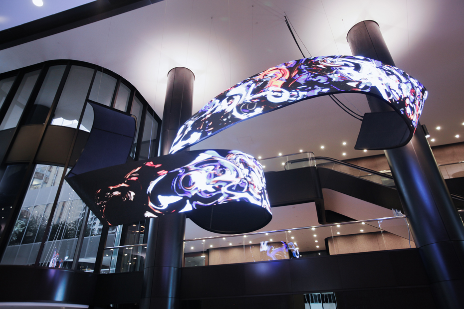
Definition
Confirm What Must Be Custom—and What Can Stay Standard
A distinctive outline alone does not require every component to be custom. First identify the non-negotiable parts of the brief—such as the visible form, active LED zones, envelope and host structure—then check whether standard modules or cabinets can satisfy them. Custom tooling or unique segmentation should be reserved for requirements that cannot be met with the standard platform.
For a project that fits a known geometry, start with its dedicated design page—such as a round, dome, sphere or triangular display—to simplify engineering and clarify the scope.
Engineering
Engineering the Geometry of Custom LED Display
Approved CAD revision
Use one controlled CAD or drawing revision as the source of truth. Record its date and approval status so mechanical design, pixel mapping, quotation and production do not refer to different concepts.
Overall bounding dimensions
Give the overall envelope in the installed orientation, including non-LED parts. Separate the visible screen dimensions from the supporting frame, trim and site clearances.
Unique part/segment count
List repeated and one-off segments, including mirrored parts and transitions. This reveals where custom fabrication, spare parts or assembly instructions may be needed.
Active LED zones
Mark every pixel-active face and any non-display areas such as seams, cutouts, caps or windows. These boundaries must agree between the mechanical drawing and controller map.
Interface to host structure
Show attachment points, allowable interfaces and any host structure supplied by others. Confirm load path, datum references and installation tolerances with the responsible project engineer.
Prototype/first-article requirement
Decide whether a prototype or first article is required before the full quantity. Use it to review fit, alignment, pixel continuity, service access and finish against agreed acceptance criteria.
Specification
RFQ Inputs for a Made-to-Drawing LED Display
| Shape-specific engineering parameter | Value | Engineering use |
|---|---|---|
| Controlled drawing revision | Project-defined / confirm by drawing | Keeps quotation, design review and manufacturing aligned to the same approved geometry. |
| Installed envelope and clearances | Project-defined / confirm by drawing | Confirms the full footprint and identifies interfaces with the surrounding site. |
| Unique segments and repeat quantities | Project-defined / confirm by drawing | Clarifies custom part scope, assembly logic, spares and production planning. |
| Active and inactive LED zones | Project-defined / confirm by drawing | Connects the physical display area to the controller map and content canvas. |
| Host structure and fixing interface | Project-defined / confirm by drawing | Allows the project team to coordinate supports, datums, access and installation responsibility. |
| Prototype / first-article plan | Project-defined / confirm by drawing | Defines what will be checked and approved before the balance of the order proceeds. |
This schedule identifies project inputs, not fixed Highcolor performance specifications. Confirm pitch, brightness, protection, module construction, electrical design and compliance requirements against the selected LED platform and installation conditions.
Content & mapping
Translate the Approved Shape Into a Pixel Map
A custom outline needs a coordinate map that matches the built display—not just an image cropped to its silhouette. Identify active zones, segment boundaries, inactive areas and the relationship between each physical section and its controller output before content production.
Ask for a test pattern or low-resolution proof using the intended map. Review seams, orientation, scaling and content safe areas across every active face, then freeze the map revision alongside the mechanical drawing.
Installation decision
Coordinate the Support, Installation and Service Plan
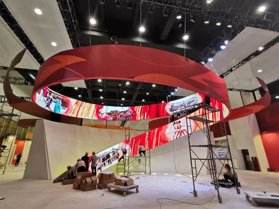
The frame and host interface must hold the agreed shape without relying on LED modules to correct structural mismatch. Define datum points, fixing locations, assembly sequence, cable paths and lifting access. Where the installation is integrated with architecture or equipment, agree who supplies each support and how the display can be reached for module or power-system service.
If standard geometry satisfies the concept, a named-form page can help narrow the design before commissioning custom engineering.
Cost drivers
What Drives the Cost of a Custom LED Display Project?
Custom pricing reflects engineering effort as well as the finished LED hardware. Unique geometry, active-zone mapping, one-off parts, structural interfaces, prototype work, finish requirements and order quantity all affect scope. A controlled drawing and clear acceptance plan reduce uncertainty before production is quoted.
Engineering Hours
More interfaces, transitions or iterations require design coordination. A stable brief and a single approved CAD revision help contain rework.
Unique Part Count
One-off shapes increase fabrication and assembly complexity. Repeated segments and mirrored parts may be planned differently from unique pieces.
Tooling/Prototype Work
A first article, mock-up or custom tooling can add an upfront step while helping verify fit, seams, finish and service access before full production.
Production Quantity
Quantity influences how engineering, setup and spare parts are allocated. Confirm expected repeat orders and replacement-part needs when requesting a quotation.
Drawing review
Review the Design Package Before Production
The design is ready for release when the visual form, mechanical envelope, LED-active zones, controller map and installation interface describe the same product. Review the points below with the relevant design, controls and site teams, then record approvals against the drawing revision.
Approved CAD revision
Check that the drawing is marked for approval and that quotation, pixel map and manufacturing files all reference the same revision. Superseded concepts should be clearly withdrawn.
Overall bounding dimensions
Verify installed width, height, depth and clearances against the host site. Confirm that the dimensions distinguish the active image from trim, frame and nearby construction.
Unique part and segment count
Reconcile the parts list with the assembly drawing. Identify repeated, mirrored and one-off sections so fabrication, packing and on-site sequencing can be planned.
Active LED zones
Confirm that every illuminated surface and every inactive gap is represented in both the mechanical layout and the pixel map. This catches missing pixels or content assigned to non-display areas.
Interface to host structure
Review fixing locations, datum points, tolerances, cable access and division of supply with the structural or architectural team before release.
Prototype / first-article requirement
Agree whether the first build will be inspected before quantity production, who approves it and which fit, image, finish and service checks define acceptance.
FAQ
Custom LED Display Engineering FAQ
When is a custom LED display preferable to a standard product?
Use a custom project when a standard cabinet, panel layout or named geometry cannot meet a necessary shape, active surface, integration or site interface. First confirm which requirement is essential; keeping suitable components standard can reduce engineering and production complexity.
What files should I send for an initial design review?
Send the concept brief, dimensioned sketch or CAD, key views, target size, active LED zones, expected viewing positions and the host structure or installation constraints. Mark the drawing revision and distinguish confirmed dimensions from open questions.
How is a custom-shaped LED screen mapped for content?
The pixel map should match the physical segment layout and identify every active and inactive zone. Review a controller test pattern across seams and transitions, then approve the map revision together with the mechanical drawing before content is finalized.
Should I request a prototype or first article?
A first article is useful when fit, surface continuity, special interfaces or finish cannot be verified from drawings alone. Agree the inspection points, acceptance criteria and approval owner before production so the prototype stage resolves the right risks.
What affects the cost and schedule of a custom LED display?
Engineering iterations, unique parts, custom supports, tooling, prototype checks, selected LED hardware and production quantity can all affect the project. A stable design brief and controlled drawing revision help reduce changes after fabrication begins.
Internal selection links
Compare Shapes With Different Engineering Intent
A circular digital sign optimized for branded messages, logos or short-form content rather than a large immersive round video surface.
A 360-degree spherical led object where latitude-like segmentation and pole treatment determine surface continuity.
A dome-shaped led surface engineered from diameter, rise and spherical segmentation to create an overhead or immersive curved image.
Request a Custom LED Display Design Review
Send the concept brief, controlled drawing or CAD, active zones, site interface, target viewing positions and prototype expectations. The team can review the technical scope before a platform and quotation are finalized.
Request Engineering Review →