360° spherical LED display · segmentation, pole closures and service design
Ball Sphere LED Screen
A Ball Sphere LED Screen is a full spherical display viewed around the object, not an overhead dome or a hemisphere fixed to a rim. Its design depends on the finished diameter, active coverage, equator alignment, pole-cap treatment and the support or suspension method. These choices shape assembly, content mapping, transport and maintenance for museums, atriums, exhibitions and other landmark spaces.
Send Drawing & Dimensions →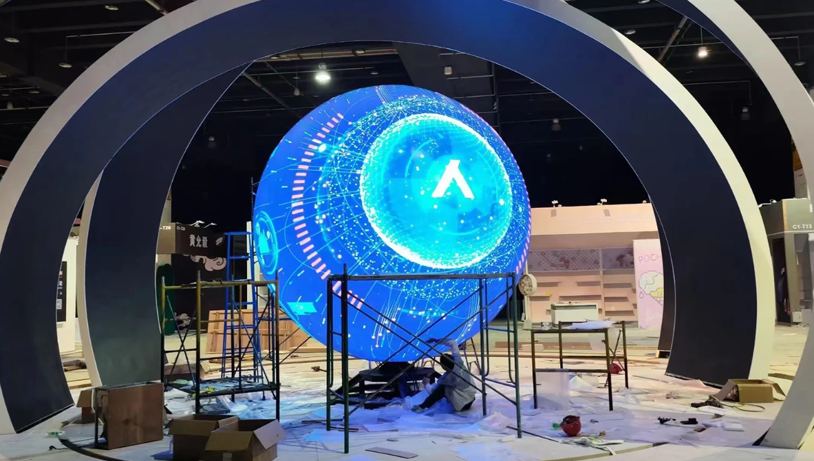
Definition
Define the 360° Surface, Pole Closures and Support Method
Start by distinguishing the visible LED surface from the complete spherical structure. Confirm whether the display is active around the full circumference, where the active area starts and ends at each pole, and whether any base, opening or support remains non-LED. A full sphere must be engineered as a coordinated assembly: segment geometry, equator reference, pole closure, structural core and pixel map all need to agree.
For a half-sphere that terminates at a defined rim plane, compare Hemisphere LED Screen. For an overhead concave surface covering only part of a sphere, see LED Dome Display.
Engineering
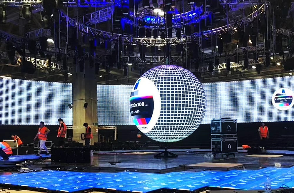
Engineering the Geometry of Ball Sphere LED Screen
Sphere diameter
Specify the finished outside diameter and separately dimension the active pixel boundary. The shell, trim and support structure can extend beyond the luminous surface.
Active coverage angle
State how much of the sphere is active and whether the surface is visible through a full 360° or only from a defined viewing zone. This sets the panel layout and edge transitions.
Equator circumference
Use the equator as a shared reference for circumference, segment alignment and controller coordinates. Confirm how the module layout closes around this ring.
Pole cap diameter
Dimension the north and south pole caps and define how their seams meet the surrounding segments. Small changes near a pole can affect both the visible pattern and the physical closure.
Segment count
Show the number and orientation of meridian or latitude segments on the assembly drawing. Tie every segment to a datum so installation order and mapping remain consistent.
Internal service opening
If the project needs an internal service opening, show its location, clear size and access route. Confirm whether components can be replaced without dismantling the finished sphere.
Specification
Drawing Inputs Required for Full Sphere Engineering
| Shape-specific engineering parameter | Value | Engineering use |
|---|---|---|
| Finished sphere diameter | Project-defined; distinguish frame and active surface | Sets the overall envelope and the relationship between the visible LED shell and its supporting core. |
| Active coverage and viewing zone | Confirm full 360° or specify inactive / restricted areas | Defines which portions require LED modules, content mapping and edge treatment. |
| Equator reference and circumference | Dimension from the approved model or fabrication drawing | Provides a common datum for aligning segments and verifying the wrap closure. |
| North and south pole-cap geometry | Project-specific cap size, seams and inactive area | Controls pole closure, segment transitions and the appearance of content near each end. |
| Meridian / latitude segmentation | Set from the approved panel layout and assembly sequence | Coordinates module boundaries, fastening, tolerances and pixel-map coordinates. |
| Support core and service access | Confirm stand / suspension interface and any actual opening | Resolves load transfer, installation access and replacement path for internal components. |
These are project engineering inputs, not fixed Highcolor product ratings. Confirm the chosen panel platform, pixel pitch, brightness, protection, weight and connection details for the intended venue.
Content & mapping
Map a Sphere Without Losing Orientation at the Poles
A spherical pixel canvas needs an explicit coordinate system. Mark the equator, pole caps, segment seams, viewing start angle and any inactive zones, then align that map with the physical assembly drawing.
Test motion, text and logos from several audience positions around the object. Artwork that looks balanced in a flat preview may stretch or converge near the poles, so review the actual mapped surface before content is approved.
Installation decision
Engineer the Core, Rigging and Assembly Sequence Together
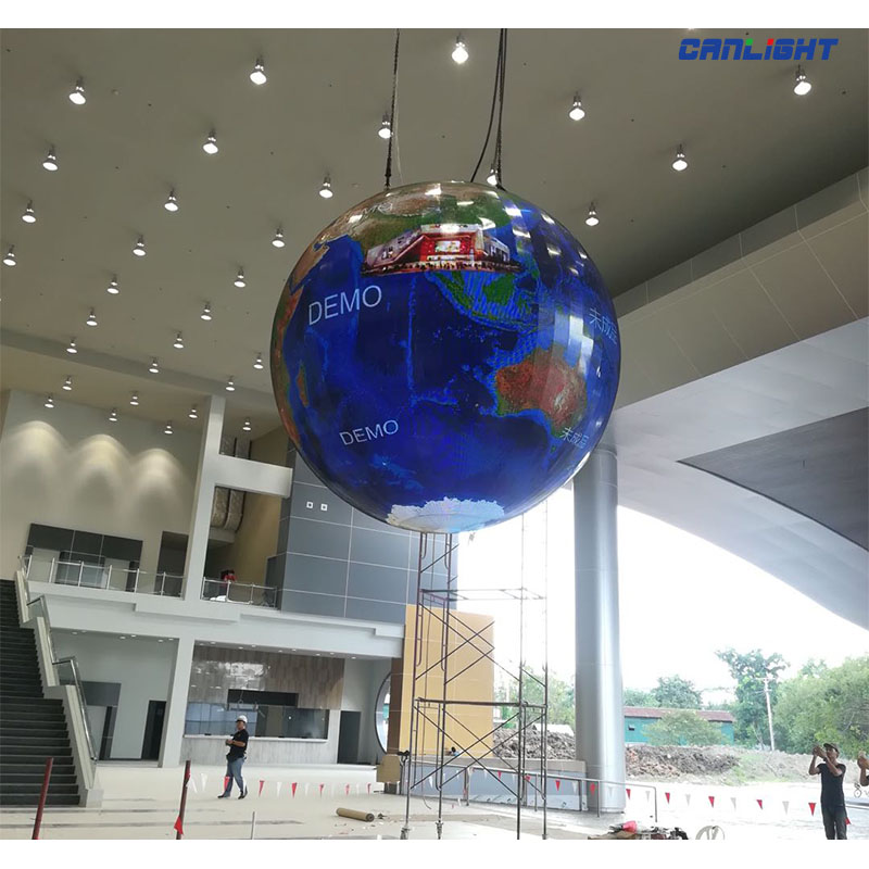
The support core must hold the sphere without distorting the panel geometry. Specify whether the unit is floor-supported, fixed to a base or suspended, and coordinate the load path, lifting points, balance, segment joints, cable routing and access with the venue structure.
Plan how the largest assembled sections will pass through doors, lifts and rigging routes. Show the assembly order and identify which panels or caps remain removable for service after the display is commissioned.
Cost drivers
What Determines the Cost of a Ball Sphere LED Screen?
Price depends on the active surface and selected LED platform, plus the custom engineering needed to close and support a spherical shape. A 3D model or dimensioned section helps identify panel segmentation, pole treatment, structure, logistics and commissioning before quotation.
Active Area & LED Platform
Diameter, coverage, pixel pitch and module format determine the core display quantity and resolution.
Segments & Pole Closures
Custom segment geometry, cap design, joints and edge finishing affect fabrication and assembly effort.
Support Core & Mounting
A stand, base or suspension system changes structural design, lifting needs and site installation scope.
Mapping, Calibration & Logistics
Polar mapping, multi-view checks, section transport and on-site alignment add project-specific work.
Drawing review
Verify the Sphere Model, Segment Layout and Pixel Map Before Production
Release the design only when the 3D model, fabrication sections and controller map use the same diameter, equator datum and segment references. Check the pole closures, support interface and access route against the real venue and installation path.
Finished diameter
Record the outer structural diameter and active LED diameter separately. Confirm both on the approved model so the frame and trim do not reduce the intended luminous area or change the final envelope.
Active coverage
Mark the viewing zones and every inactive surface, including the base, support and pole caps. This avoids mapping content across areas that will not carry pixels.
Equator datum
Use one defined equator line on the mechanical drawing and controller map. Check the circumference and segment closure against that same datum before freezing the layout.
Pole-cap geometry
Show the cap size, seam positions and transition to the surrounding segments at both ends. Review how imagery and text behave as they approach the poles.
Segment orientation
Number and orient every segment in the assembly drawing. The installation team and content team should use the same identifiers when locating seams and addressing pixels.
Support and access
Confirm how the core transfers load to the base or host structure and how service components remain reachable. Validate lifting, delivery and replacement routes against the venue constraints.
FAQ
Ball Sphere LED Screen Questions
What drawing is needed to quote Ball Sphere LED Screen?
Send a dimensioned sketch, CAD model or elevation showing sphere diameter, active coverage angle and the active LED area. A reference image alone is not enough for final engineering.
Which geometry dimension controls Ball Sphere LED Screen most strongly?
Start with sphere diameter and active coverage angle. The engineering team also needs equator circumference before module segmentation is frozen.
How should pixel mapping be prepared for Ball Sphere LED Screen?
Map the real active surface rather than forcing a standard 16:9 canvas. The controller map should follow the approved geometry, seams and inactive zones of this full sphere engineering project.
What service-access issue is specific to Ball Sphere LED Screen?
Access must be planned around internal service opening. Components that become trapped behind the finished geometry should be identified before the support structure is released.
What usually changes the cost of Ball Sphere LED Screen?
The largest geometry-related variables are sphere diameter, pole/segment complexity, support core and custom mapping and calibration. LED pitch and total active area also affect the final quotation.
Internal selection links
Compare Shapes With Different Engineering Intent
A spherical led display specified as a finished visual object, with emphasis on project sizing, support method and viewing around the ball.
A half-spherical led surface with a defined rim plane, projection depth and mounting interface.
A dome-shaped led surface engineered from diameter, rise and spherical segmentation to create an overhead or immersive curved image.
Request a Sphere Layout and Engineering Review
Share the 3D model or dimensioned sections, active coverage, equator and pole details, mounting plan, viewing positions and service-access requirements for a coordinated mechanical and pixel-map review.
Request Engineering Review →