freestanding digital pillar · project engineering
LED Pillar
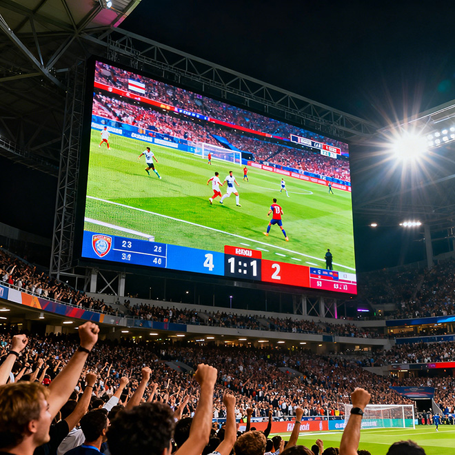
A freestanding LED pillar is a self-supporting vertical display designed as an architectural feature. Its proportions, viewing sides, base interface, structural support and service access need to be coordinated as one project—from the first drawing through content mapping and installation.
Request a project review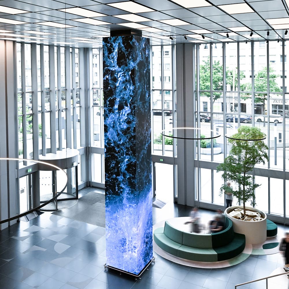
Definition
Define the Freestanding Digital Pillar Before Choosing Modules
A freestanding LED pillar is a self-supporting display object with its own frame or base. It is planned around site dimensions, viewing directions, support, service access and the active pixel surfaces. A finished floor-standing signage unit or an LED screen wrapped around an existing building column is a different product type.
This page covers project-engineered, self-supporting LED pillars. For a standalone digital totem, see LED Totem; for a display fitted around an existing building column, see Column LED Screen.
Which LED pillar format fits your project?
The name is used for several different products. Identify the installation type first: it determines whether the display needs a custom support structure, a standalone totem enclosure or integration with an existing column.
Freestanding LED Pillar
A project-engineered vertical LED object with its own support and base. This page focuses on geometry, site interface, active faces, service access and content mapping.
LED Totem
A standalone digital totem is a separate route for wayfinding, advertising or event signage. Confirm whether the selected model is fixed or mobile and which processing and setup features it includes.
View LED TotemLED screen for an existing column
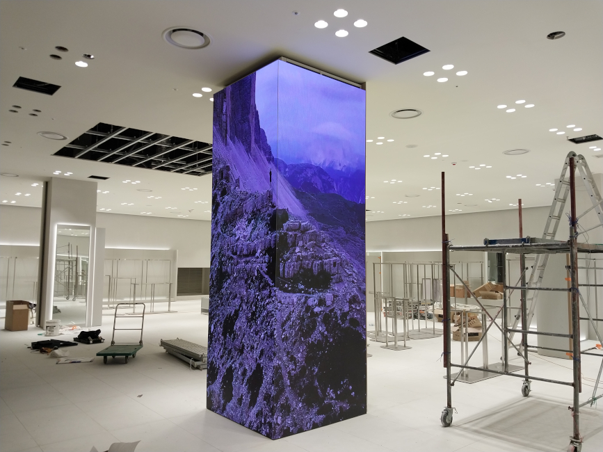
A column wrap uses the building's existing column as its host geometry. Measurements, attachment and service access differ from a self-supporting LED pillar.
View Column LED ScreenEngineering
Match viewing distance, lighting and content to the display system
Viewing distance and detail
Use the closest normal viewer position and the smallest text or graphic detail to guide pixel-pitch and resolution discussions. Request a sample or calculation based on the actual viewing distance.
Viewing directions
Map the main approach routes and decide which faces need pixels. Multi-face objects require content planning at corners; additional active sides also affect area, control and service scope.
Ambient light and exposure
Record indoor lighting, nearby windows, glare and direct sunlight. Confirm the usable brightness range and verified protection for the exact indoor or outdoor configuration.
Content behavior
Decide whether faces repeat one image, show independent content or carry one continuous composition. Include a controller map and test artwork across seams and inactive surfaces.
Maintenance and duty cycle
Confirm operating hours, front or rear service approach, access-panel locations and the replacement method. Do not assume a maintenance method before choosing the enclosure.
Installation environment
Record floor level, public access, cable entry, cleaning practice and temperature or moisture exposure. Specify only tested product limits for the selected configuration.
Specification
Drawing Inputs Required for Freestanding Digital Pillar
| Project input | Drawing or specification details to confirm |
|---|---|
| Pillar overall height | Show finished floor-to-top height and distinguish the full object from the active LED area, top and bottom trim, and installation clearances. |
| Pillar cross-section | Provide plan dimensions or diameter, face widths, corner radius or miter, and the intended transitions between display faces. |
| Base footprint | Mark the base footprint, floor or host interface, fixing area, cable entry and any concealed plinth or trim. |
| Number of active sides | State which faces are active, their orientation to the audience, and any blank, access or non-display face. |
| Top/bottom finishing | Detail visible borders, cap profiles, trim, inactive zones and alignment with the surrounding finish. |
| Support and anchoring details | Show the proposed support and anchoring interface, installation method and service access. Project structural adequacy must be reviewed for the actual site. |
These are project inputs, not preset Highcolor performance specifications. Confirm dimensions, pixel pitch, brightness, protection, construction and controller details for the selected product configuration.
Content mapping
Map content to the approved active display surface
Finished media should follow the real active geometry. Seams, corners, caps, cutouts or inactive zones must be represented in the controller map before final content is produced.
The playback canvas should follow the approved physical layout—not assume a standard 16:9 video across the full installation. Confirm whether artwork repeats, wraps around corners or is assigned separately to each face.
Map each active face
Record width, height and usable pixels for every display face. Mark corners, seams, caps, cutouts and non-display areas so content follows the real surface.
Set the playback canvas
Confirm whether content is repeated, wrapped or assigned independently to each face. Align the media canvas with the controller configuration before creating final artwork.
Test sightlines and transitions
Review the map from the intended viewer positions and check how imagery crosses corners or changes face. Adjust content where geometry interrupts important text or logos.
Installation decision
Coordinate support, installation sequence and service access
The support design should hold the approved geometry without relying on LED modules to correct structural errors. Confirm the floor or host structure, anchor locations, datums, segment joints, cable routes, installation sequence and service clearances in coordinated drawings. Structural adequacy and anchoring must be reviewed for the actual site and applicable requirements.
For a screen that wraps around an existing structural column, see Column LED Screen. That solution depends on the host column; a freestanding pillar has its own support and base interface.
Cost drivers
What Affects an LED Pillar Project Cost?
Request an itemized quote that separates the LED display package from custom fabrication, site work and commissioning. The approved drawing, configuration and installation conditions determine the actual scope.
LED display package
List active display area, pixel pitch, face count, control system, power supplies, required protection and included spare modules. Tie each item to the selected configuration and its datasheet.
Support and finish
Separate frame, base, anchoring interface, cladding, caps, corner treatments and architectural finish. Clarify who supplies and approves the support structure.
Site installation and logistics
Include packing, shipping, customs if applicable, venue access, lifting or handling, cabling, installation labor and electrical or network coordination.
Commissioning and lifecycle
Include controller mapping, image calibration, content testing, handover, operator training, warranty, maintenance access and recommended spare parts.
Drawing review
Production drawing approval: four release checks
Before fabrication, review one coordinated package across geometry, site interface, media mapping and service. These checks reduce interpretation gaps between the display supplier, structural designer, installer and content team.
Freeze geometry and active area
Approve overall height, plan or cross-section, active pixel area, face orientation, corner treatment and all non-LED borders. Keep the physical envelope and pixel canvas distinct on the controlled drawing.
Coordinate the site interface
Verify site dimensions, base footprint, support and anchoring responsibility, cable route, access panels and installation clearances. Route site-specific structural and building requirements to the responsible design and approval parties.
Approve content and control mapping
Match the active faces and pixel layout to the controller configuration. Test representative content across seams and corners, and agree the source format, playback behavior and revision owner.
Release service and commissioning plan
Document component access, post-installation checks, image and mechanical alignment sign-off, recommended spares, handover records and operator training.
A project path that keeps design, content and installation aligned
A custom pillar is easier to quote and deliver when the owner, display supplier, structural designer and installer work from the same controlled information.
1. Define the brief
Confirm venue, audience routes, purpose, overall size, active faces, viewing distance, content type and operating hours.
2. Verify the site
Record floor and nearby structure, delivery access, installation clearances, power and data routes, service access and local approval needs.
3. Freeze the design
Approve coordinated geometry, display specification, support interface, pixel map, control method, finish, responsibilities and quotation scope before production.
4. Install and sign off
Test content from key viewer positions, inspect seams and alignment, verify control and service access, then complete handover and maintenance records.
FAQ
LED Pillar: project planning questions
What drawing is needed to quote LED Pillar?
Send a dimensioned sketch, CAD model or elevation showing pillar overall height, pillar cross-section and the active LED area. A reference image alone is not enough for final engineering.
Which geometry dimension controls LED Pillar most strongly?
Start with pillar overall height and pillar cross-section. The engineering team also needs base footprint before module segmentation is frozen.
How should pixel mapping be prepared for LED Pillar?
Map the real active surface rather than forcing a standard 16:9 canvas. The controller map should follow the approved geometry, seams and inactive zones of this freestanding digital pillar project.
How should maintenance access be planned?
Identify which components require inspection or replacement and show how a technician reaches them after the finish panels and display are installed. Keep access panels, clearances and safe working space in the coordinated drawings.
What usually changes the cost of LED Pillar?
The largest geometry-related variables are overall height, cross-section and active sides, base structure and decorative finishing. LED pitch and total active area also affect the final quotation.
Related LED display solutions
Explore related creative LED formats
A curved LED surface mounted around an existing cylindrical or faceted column. The host structure defines geometry and support.
A four-sided display fitted around a square or rectangular host column, with defined face widths and corner transitions.
A branded cylindrical form with project-defined proportions, active area, support and top/bottom finish.
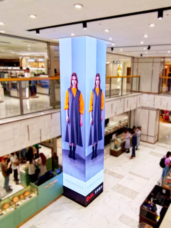
This installation wraps an existing structural column. A freestanding LED pillar is engineered with its own support and base; the two concepts require different site measurements and structural coordination.
Request a project review for your LED Pillar
Send the intended site, dimensioned plan and elevation, viewing distances, active face count, indoor or outdoor conditions, support interface and service-access needs. We can review the scope and identify which configuration details still need confirmation.
Request Engineering Review →