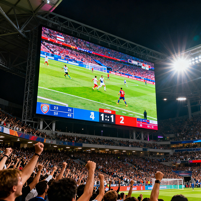
Freeform LED surface · geometry, mapping and installation
Irregular LED Display
Irregular LED Display describes a custom LED surface whose outline or form does not follow a standard rectangle, circle, column or repeatable polygon. Projects may use stepped flat modules, shaped edge details, curved segments or a combination. The first decision is whether the irregularity belongs to the physical screen surface, its outer silhouette, or only the content; each path changes the frame, pixel map, viewing result and service plan.
Review a Freeform Drawing →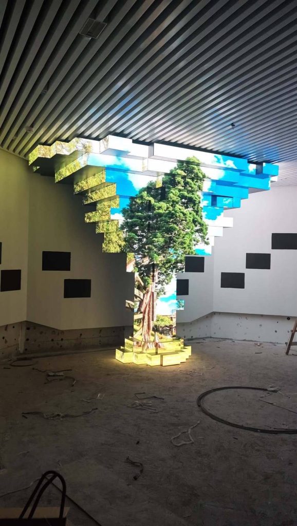
Definition
Separate the screen outline, surface shape and content mask
A freeform concept image does not show how the display will be built. Establish a controlled perimeter drawing, maximum envelope and surface profile, then mark active pixels, cut-outs and non-display areas. Confirm if the form is planar, segmented or curved and which faces the audience will see. This prevents the design team from treating a visual silhouette as proof that every edge can be fabricated from standard modules.
If the geometry resolves to a repeatable shape such as a triangle, cube or arch, use that dedicated format. Irregular LED Display is for outlines or surfaces that need a project-specific layout.
Engineering
Engineering the Geometry of Irregular LED Display
Perimeter CAD/DXF
Provide a scaled closed perimeter in CAD/DXF and identify the origin, orientation and datum points. Show the active LED edge separately from trim, frame and support so everyone works from the same boundary.
Maximum W × H × D
State the maximum width, height and depth, including the rear structure and access allowance. A front elevation alone cannot confirm the installation envelope or clearances.
Concave/convex zones
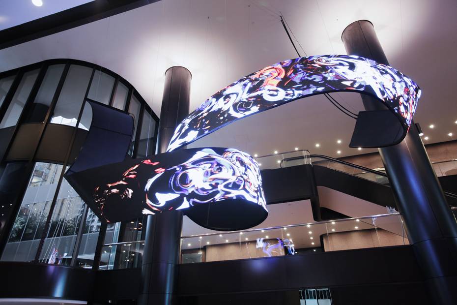
Mark each zone as flat, concave, convex, segmented or cut. For every curved zone, confirm the intended radius or segment method against the selected module system before freezing the design.
Minimum local feature width
Identify the narrowest active section, tip or neck in the outline. Its width affects whether pixels and modules can represent the shape cleanly without making the form fragile or visually jagged.
Active/inactive cutout map
Show where pixels are active and where the outline contains gaps, holes, seams or masked regions. Content and controller mapping must follow this surface map rather than fill the bounding rectangle.
Segmentation datum points
Add repeatable registration points and segment numbers to the drawing. These references support fabrication, assembly, signal mapping and later replacement of a section.
Specification
Geometry and display details required for an RFQ
| Shape-specific engineering parameter | Value | Engineering use |
|---|---|---|
| Scaled perimeter and datum | Project-defined / confirm by drawing | Supply a closed vector outline with origin, orientation, scale and control points; separate the LED edge from trim and structure. |
| Overall envelope and depth | Project-defined / confirm by drawing | Give maximum width, height and installed depth, including support frame, cable path and service clearances. |
| Surface zones and curvature method | Project-defined / confirm by drawing | Label flat, segmented, concave, convex and cut-out areas; confirm radii or facets with the selected construction approach. |
| Minimum feature width and edge detail | Project-defined / confirm by drawing | Dimension narrow sections, tips and notches so the pixel grid and module edges can be checked against the silhouette. |
| Active pixel mask and openings | Project-defined / confirm by drawing | Map active areas, seams, holes and inactive surfaces to the controller canvas and content plan. |
| Segment references and service plan | Project-defined / confirm by drawing | Number the sections, show attachment points and state how each module or segment can be reached and replaced. |
This is a design and quotation checklist, not a published Highcolor specification. Confirm pixel pitch, brightness, refresh, protection level, curvature limits, module construction and control configuration for the final shape.
Surface map and content
Build the pixel canvas from the approved surface map
A freeform display may have a rectangular controller canvas with pixels only in selected regions. The blank pixels outside the silhouette and inside openings must be handled deliberately in the content file. For a curved or multi-plane form, the map also needs each face's orientation, pixel order, seam and viewing direction.
Before final artwork, test the mapped surface with a grid, perimeter line and moving object. This reveals reversed segments, discontinuities and content that disappears into a cut-out. Keep the controller map, segment labels and fabrication drawing under the same revision so changes to the shape are reflected in the media.
Installation decision
Choose a build method that supports the shape and future service
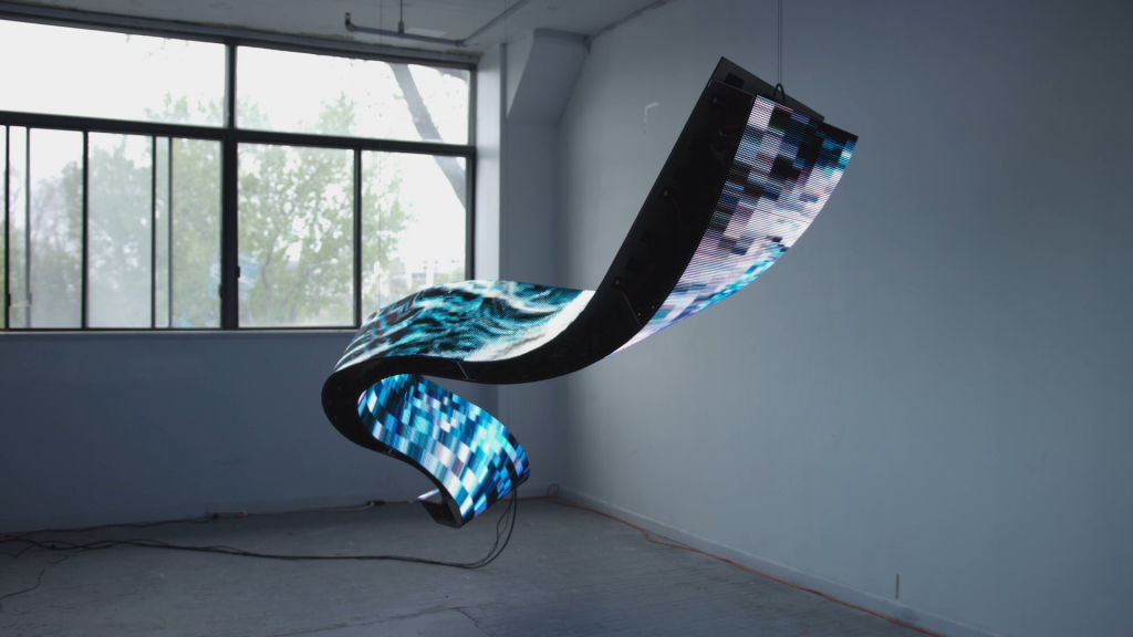
The outline can be achieved with stepped standard modules, custom edge treatment, curved or faceted segments, or a combination; the suitable approach depends on the selected platform and required viewing result. Design the support frame and assembly datums around the actual module boundaries. Preserve access to power, signal and replaceable modules, and plan how the assembly will be transported and lifted into the venue.
For an object built from repeatable square faces, compare Cube LED Display. For a specific continuous curve, consider a curved or flexible LED format.
Cost drivers
What determines the cost of an Irregular LED Display?
Price depends on active pixel area and pitch as well as the number of unique segments, edge complexity and surface transitions. A simple stepped outline can have a different scope from a curved sculpture with cut-outs. The frame, access method, content mapping, control outputs and site installation also matter. A scaled drawing and section views make the quote more accurate than a concept render alone.
Outline and edge complexity
More notches, narrow tips and unique perimeter segments require closer fit and edge-detail coordination.
Unique zones and surface transitions
Different planes, curves, openings and inactive areas add module layout and mapping work.
Support frame and installation
The structure, segment registration, transportation and site assembly depend on the form and venue.
Pixel map and commissioning
Each independent surface zone must be mapped, tested and aligned with its corresponding content.
Drawing review
Review the geometry, map and structure as one package
Before release, confirm that the outline drawing, module segmentation, support detail and pixel map describe the same revision. Check narrow features, edge treatment and cut-outs against actual module dimensions and the selected platform. Then walk through the assembly and maintenance sequence: a shape is only practical when the sections can be installed, connected and serviced in the real venue.
Perimeter and maximum envelope
Check the scaled outline, maximum dimensions, depth and installation clearance. Confirm whether the active boundary follows the external edge or leaves a trim or non-display border.
Local features and edge resolution
Review narrow tips, necks, notches and small openings at the intended viewing distance. Verify that the chosen module arrangement can produce the outline without unsupported assumptions about custom pixel shapes.
Curvature, facets and surface transitions
Identify where the design changes plane or direction. Confirm the construction method, seam locations and audience view for each transition before content is produced.
Active zones and controller mapping
Cross-check segment IDs, pixel direction, inactive pixels, cut-outs and signal connections between the fabrication drawing and controller file.
Frame, transport and assembly
Confirm attachment points, segment size, lifting path and assembly order against site access. Keep the frame stable without making serviceable areas inaccessible.
Service access and replacement
Record how a module or section is removed, where power and data components are located, and how the repaired section returns to the same alignment datum.
FAQ
Irregular LED Display: common questions
What files should I provide for an Irregular LED Display quote?
Send a scaled perimeter in CAD/DXF, elevations or a 3D view, overall envelope, surface profile, active pixel areas, cut-outs, viewing positions, mounting conditions and site access details. Identify the intended display faces and whether the contour is stepped, curved or multi-plane.
Does an irregular outline require custom LED modules?
Not always. Some outlines can be created from standard modules arranged in a stepped pattern, while other designs need custom edge details, curved sections or a combination. The appropriate approach depends on the pixel pitch, module platform, silhouette and viewing distance; confirm feasibility against the selected product configuration.
How do content and pixel mapping work on a non-rectangular screen?
The controller canvas can remain rectangular while active pixels occupy only a defined mask. The map should label each segment, its pixel direction, seams, inactive areas and signal path. Test it with a grid and moving line before final content so reversed or missing zones are caught early.
Can a freeform LED display include concave or convex areas?
That depends on the chosen module and support system. Define each zone as flat, faceted or curved and provide its radius or section detail for review. Do not assume that a flexible module can meet every contour or installation condition without checking the product limits.
What affects the cost of a custom irregular LED screen?
Active area and pixel pitch are part of the estimate, along with the number of unique segments, edge complexity, curves or cut-outs, support frame, installation access and controller mapping. A dimensioned drawing helps distinguish a simple stepped silhouette from a more involved sculptural surface.
How should the display be serviced after installation?
Plan module access, section removal, cable routes and alignment references before the frame is closed. The service plan should explain how a repaired section can be reinstalled in the correct position and how technicians reach power and signal components in the venue.
Related creative LED formats
Compare the geometry before choosing a display type
An led media layer integrated with the architectural façade or secondary façade system, where attachment, openness and envelope coordination are primary.
An led display forming an overhead arch or portal around a passage, with clear opening and curved/segmented soffit as primary constraints.
A multi-face led object built around square faces meeting at controlled 90-degree edges.
Start with a scaled outline and surface definition
Share a CAD/DXF outline, elevations or 3D views, active pixel areas, surface transitions, viewing positions, mounting conditions and venue access. Highcolor can review the geometry, segmentation, pixel map and information needed for a project quotation.
Request Engineering Review →