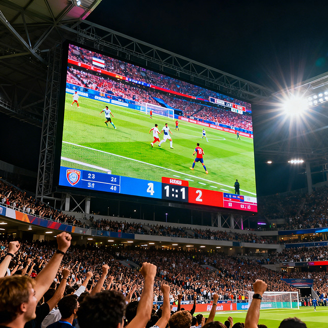
Multi-face LED object · engineered to the approved drawing
Cube LED Display
Build a cube-shaped display around its real geometry: side length, active faces, corner construction and per-face pixel mapping. Clear drawings help coordinate the LED surface, support structure and content before fabrication begins.
Send Drawing & Dimensions →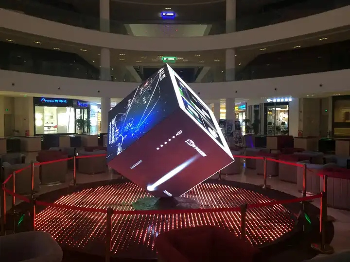
Definition
Define the Multi-Face Cube Before Choosing Modules
The defining question is not simply whether the screen looks unusual. For this page, the project must be treated as multi-face cube. That changes the drawing inputs, segmentation, support and content map used for engineering.
For only two perpendicular faces, Corner LED Screen is usually the more direct page.
Engineering
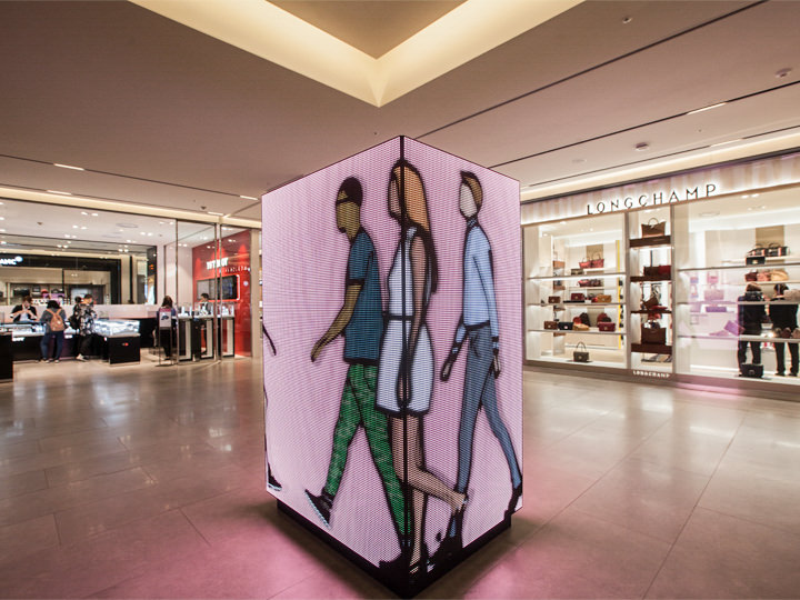
Engineering the Geometry of Cube LED Display
Cube side length
This dimension establishes the primary geometric envelope and should be fixed on the approved drawing.
Number of active faces
This controls how the active LED surface is divided, supported or viewed in the finished installation.
Edge seam allowance
This value affects segmentation and should be coordinated with the intended viewer or host structure.
Corner construction type
Record this explicitly so production does not infer the geometry from a concept rendering.
Per-face pixel matrix
This parameter helps define repeatable assembly references, alignment and the real pixel canvas.
Suspension/base load path
Maintenance must remain possible after the decorative structure and LED surface are fully installed.
Specification
Drawing Inputs Required for Multi-Face Cube
| Shape-specific engineering parameter | Value | Engineering use |
|---|---|---|
| Cube side length | Project-defined / confirm by drawing | Required to engineer the multi-face cube geometry before production. |
| Number of active faces | Project-defined / confirm by drawing | Required to engineer the multi-face cube geometry before production. |
| Edge seam allowance | Project-defined / confirm by drawing | Required to engineer the multi-face cube geometry before production. |
| Corner construction type | Project-defined / confirm by drawing | Required to engineer the multi-face cube geometry before production. |
| Per-face pixel matrix | Project-defined / confirm by drawing | Required to engineer the multi-face cube geometry before production. |
| Suspension/base load path | Project-defined / confirm by drawing | Required to engineer the multi-face cube geometry before production. |
These are RFQ/engineering fields, not claimed Highcolor performance specifications. Exact dimensions, pitch, brightness, protection and module construction must be confirmed for the selected product platform.
Content & mapping
Build the Pixel Canvas Around Cube side length
Finished media should follow the real active geometry. Seams, corners, caps, cutouts or inactive zones must be represented in the controller map before final content is produced.
For multi-face cube, the useful canvas is defined by the approved physical layout—not by automatically stretching a rectangular 16:9 video across the installation.
Installation decision
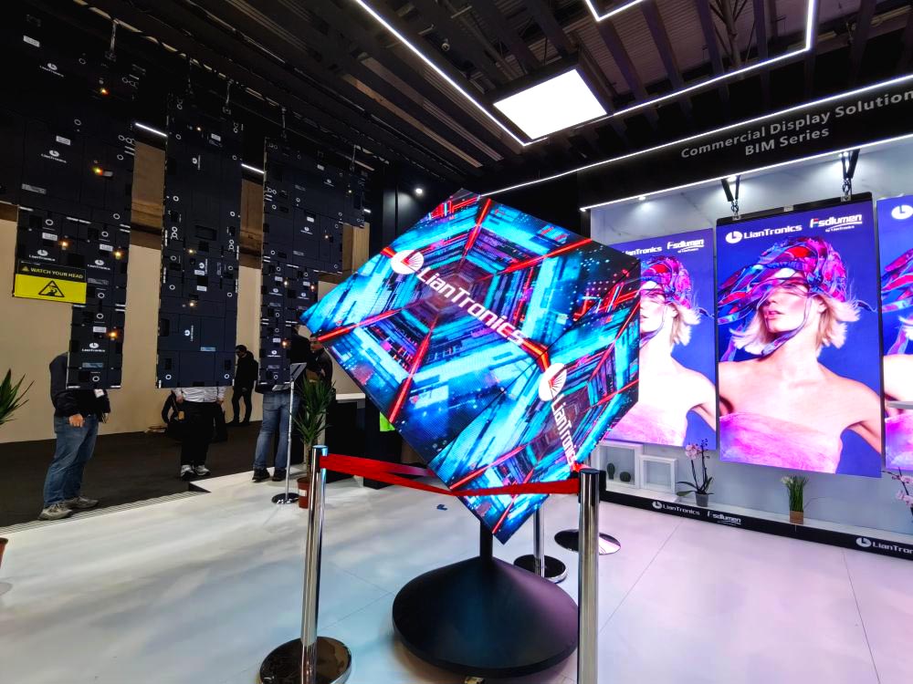
Choose Structure and Service Access for Suspension/base load path
The support design should hold the intended geometry without forcing LED modules to correct structural errors. Establish datums, segment joints, installation sequence and service clearances from the project drawing.
For only two perpendicular faces, Corner LED Screen is usually the more direct page.
Cost drivers
What Changes the Cost of This Multi-Face Cube Project?
Budget movement for cube led display is driven mainly by number of active faces, corner treatment, independent versus continuous face mapping and suspension or pedestal structure. Final pricing needs an approved drawing and selected LED platform.
Number Of Active Faces
Changes fabrication and segmentation effort for this shape.
Corner Treatment
Changes the amount or density of hardware required.
Independent Versus Continuous Face Mapping
Changes structural, tooling or installation work.
Suspension Or Pedestal Structure
Changes commissioning, mapping or finishing effort.
Drawing review
How to Review the Cube LED Display Drawing Before Production
The drawing review for Cube LED Display should be organized around its own geometry rather than a generic creative-screen checklist. The six items below are the minimum shape controls used to turn the concept into measurable fabrication and installation information.
Cube side length
Cube side length is a controlling envelope dimension for Cube LED Display. Use the installed finished dimension and identify any trim, structural clearance or non-LED border separately so the active pixel area is not confused with the overall object size. The approved value should be shared by mechanical, control and content teams.
Number of active faces
Number of active faces defines where real pixels exist on Cube LED Display. This input belongs in both the mechanical drawing and controller map so content production does not assume pixels in seams, caps, cutouts or inactive faces. Tolerance should be agreed where neighboring architecture or decorative finishes are already fixed.
Edge seam allowance
Edge seam allowance governs the visual transition between surfaces. Review it from the priority viewing positions because a mechanically acceptable joint can still create a visible interruption in continuous media. A site measurement and fabrication drawing should resolve any conflict before manufacturing.
Corner construction type
Corner construction type governs the visual transition between surfaces. Review it from the priority viewing positions because a mechanically acceptable joint can still create a visible interruption in continuous media. This is one of the dimensions that should appear in the RFQ rather than being left to supplier interpretation.
Per-face pixel matrix
Per-face pixel matrix defines where real pixels exist on Cube LED Display. This input belongs in both the mechanical drawing and controller map so content production does not assume pixels in seams, caps, cutouts or inactive faces. Changing it late can affect several downstream parts, so revision control matters.
Suspension/base load path
Suspension/base load path connects the LED assembly to the host structure. Its location should be coordinated with structural reactions, installation sequence and tolerances before production drawings are released. For replacement or retrofit work, measure the existing condition instead of relying only on legacy drawings.
FAQ
Cube LED Display Engineering FAQ
What drawing is needed to quote Cube LED Display?
Send a dimensioned sketch, CAD model or elevation showing cube side length, number of active faces and the active LED area. A reference image alone is not enough for final engineering.
Which geometry dimension controls Cube LED Display most strongly?
Start with cube side length and number of active faces. The engineering team also needs edge seam allowance before module segmentation is frozen.
How should pixel mapping be prepared for Cube LED Display?
Map the real active surface rather than forcing a standard 16:9 canvas. The controller map should follow the approved geometry, seams and inactive zones of this multi-face cube project.
What service-access issue is specific to Cube LED Display?
Access must be planned around suspension/base load path. Components that become trapped behind the finished geometry should be identified before the support structure is released.
What usually changes the cost of Cube LED Display?
The largest geometry-related variables are number of active faces, corner treatment, independent versus continuous face mapping and suspension or pedestal structure. LED pitch and total active area also affect the final quotation.
Internal selection links
Compare Shapes With Different Engineering Intent
A visual background layer designed around camera, stage or display composition rather than a standalone geometric object.
A half-spherical led surface with a defined rim plane, projection depth and mounting interface.
A tree-inspired led sculpture combining trunk, branch/canopy geometry and digital surfaces into a landmark installation.
Quote Cube LED Display From the Drawing, Not the Name
Send the geometry, dimensions, viewing distance, indoor/outdoor condition, mounting interface, content concept and service-access requirement.
Request Engineering Review →