ROTATING LED INSTALLATIONS · PROJECT ENGINEERING
LED Rotating Display
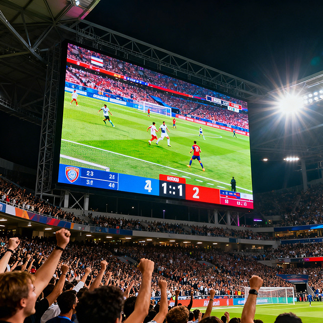
A rotating LED display uses a motorized axis to change the screen’s orientation or reveal different faces to viewers. Common concepts include a suspended double-sided screen, a rotating tower, or independently driven layers. The display, drive, support, cable transfer, controls and service route must be reviewed together.
Send Drawing & Dimensions →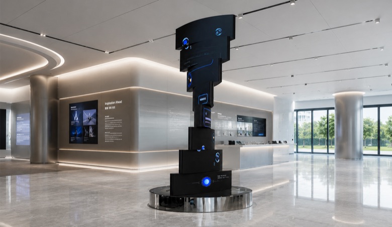
Choose the display architecture
Which rotating screen format fits the viewing space?
A single-body unit rotates one complete screen to address changing audience directions. A double-sided suspended display keeps content visible on both faces as it turns. A multi-layer tower can rotate sections independently, changing the object’s shape as well as its orientation. Select the format from the audience sightlines and intended motion—not from appearance alone.
Then decide how it should move: continuous rotation, indexed stops, or limited-angle oscillation. Continuous full turns require a suitable power/data transfer interface; indexed or limited travel may allow a managed cable path. The selected motion profile, complete moving load and venue structure determine which solution is practical.
Format selection
Start with the audience view, then choose how the screen rotates
The three common arrangements solve different visibility and motion problems. This comparison helps establish the project brief before dimensions, pixel pitch and mechanical details are fixed.
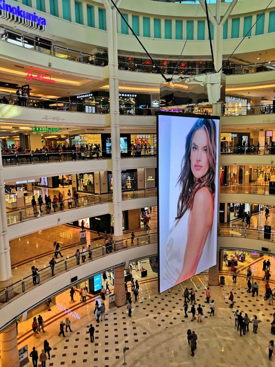
Suspended double-sided screen
Best when two audience directions need a live image. Confirm face visibility, suspension/hoist loads, rotation range and maintenance position; the venue structure must support the complete moving assembly.
Single-body rotating display
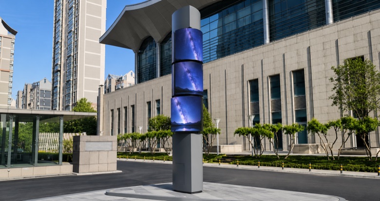
A fit for a tower, column or screen that turns as one unit to reveal changing faces. Specify its swept diameter, axis, viewing distance and whether it must rotate continuously or stop at set positions.
Independently rotating layers
Use when the display should change from one aligned surface into a stepped or sculptural composition. Each layer adds control, cable, balance and service interfaces that need to be coordinated in the drawing.
Motion & structure
Engineering inputs that determine the rotating assembly
Rotation axis & support
Show the shaft or bearing centerline, attachment points and the structure that carries the rotating assembly. A small axis offset can change clearances and balance.
Rotating envelope
Dimension the outermost moving edge through a full revolution, including frames, service covers and attached cables. Check the complete swept area against the venue.
Angle & operating mode
State whether the unit turns continuously, indexes to set positions, oscillates within a limited angle or uses independent layer movement.
Speed, acceleration & duty
Define rotation speed, start/stop behavior, dwell time and daily cycle count. These inputs affect drive sizing, control behavior, user comfort and commissioning.
Mass & balance
Provide the complete moving mass and its distribution around the axis. Uneven mass can create vibration, bearing stress and a less predictable stop.
Power/data transfer & access
Identify which signals and power must cross the rotating interface, how service access is reached and what safe state is required during maintenance.
RFQ inputs
What to Include in a Rotating LED Display RFQ
| Design input | What to provide | Why it matters |
|---|---|---|
| Rotation layout | Single-body or multi-layer; one or two display faces; fixed or independently driven sections. | Defines the system architecture, display surfaces and motion-control scope. |
| Axis & envelope | Axis position, overall height/width, maximum swept diameter and adjacent obstructions. | Supports clearance checks for a full turn and informs the structure and venue review. |
| Motion profile | Continuous/indexed/limited-angle motion, target speed, acceleration, dwell positions and operating cycles. | Helps evaluate drive, braking, control sequence and required test cycles. |
| Complete moving load | Screen, frame, shaft attachments, cable assemblies and any covers; provide load distribution if known. | Enables preliminary structural, bearing, rigging and balance review. |
| Power, data & signal | Required feeds, processor/server, control interface, cable route and whether full-turn operation is required. | Determines how services cross the rotating boundary and which supplier owns each connection. |
| Venue & maintenance | Indoor/outdoor location, suspension or foundation details, access method, service windows and local constraints. | Affects installation method, environmental protection, isolation and lifecycle access planning. |
These are project inputs rather than claimed Highcolor product specifications. Final dimensions, pixel pitch, brightness, protection, drive, rotation speed and permissible loads depend on the selected display and site engineering.
Display & content mapping
Make every viewing side part of the content plan
For a double-sided unit, decide whether both faces show the same program, separate messages or complementary frames. For a layered tower, map each face and layer to its physical position and movement state. Specify viewing directions and sightlines so the content remains intentional as the display turns.
Review seams and orientation at the parked positions as well as during motion. Content timing, rotation cues and any index/hold positions should use a shared reference so the screen does not reveal a blank or misaligned face unexpectedly.
Installation & service planning
Engineer the rotating interface before the display is fabricated
The rotating assembly needs a defined structural load path from the screen through its shaft, bearing or suspension into the building or support frame. The venue engineer should review dead load, motion effects, attachment details and any hoist or secondary-retention system. Keep installation tolerances and alignment datums on the controlled drawing.
Treat the rotating boundary as a system interface: power and data transfer, motion control, position feedback, emergency stop and isolation should have named owners. Plan a safe maintenance position and a way to reach the drive, bearings and display components without relying on ad hoc access equipment.
Cost planning
What affects the cost of a rotating LED display?
The budget depends on more than the LED area. The rotation format, complete moving load, support or hoist, cable-transfer approach, control integration and venue access can all change the scope. A dimensioned layout and motion profile are the best starting point for a useful estimate.
Rotating format
A single rotating body, double-sided screen, suspended unit or independently driven layers require different structures and drive arrangements.
Display area & faces
Screen size, pixel pitch, number of active sides and custom geometry define the LED package and content-mapping work.
Drive & service interface
Drive, bearing, position sensing, braking and power/data transfer are project-specific; continuous rotation may require a different interface from limited travel.
Venue integration
Rigging or foundation work, hoisting, access equipment, installation windows, safety integration and commissioning affect site costs.
Production drawing review
Review rotation, display and venue interfaces as one set
A release drawing should show the stationary and moving conditions, define the mechanical and electrical boundaries, and give the venue team a safe installation and maintenance plan. The checklist below focuses on the decisions that most often change after a concept rendering becomes a buildable system.
Axis, sweep & clearances
Check the axis location and full swept envelope in plan and elevation. Include handles, frames, covers, cable loops and the space required for installation and servicing.
Loads, balance & support
Review complete assembly mass, its distribution, shaft/bearing arrangement, building or truss attachment and secondary retention with the responsible engineer.
Rotation mode & stops
Confirm continuous versus indexed or limited-angle motion, speed profile, reference position, braking and behavior after loss of power or control.
Cable and signal route
Show how power, LED data and control cross the rotating interface. Confirm compatibility with the required travel and define who supplies and tests each part.
Faces, seams & pixel map
Verify active faces, orientation, viewing directions, seams and content states at each hold position. Include a mapping file or drawing tied to the physical build.
Access, isolation & recovery
Identify a safe service position, isolation point, access equipment, replaceable parts and recovery procedure if the screen stops between indexed positions.
Common questions
LED Rotating Display: project questions
What information is needed to quote a rotating LED display?
Share the overall dimensions, rotation axis and envelope, number of display faces, motion mode, target speed, approximate complete moving load, venue structure and expected operating cycle. Include the LED processor/media-server and control equipment if already selected.
Can the display rotate continuously through 360 degrees?
That depends on the mechanical design and the power/data transfer interface. Continuous rotation and limited-angle motion have different cable and control requirements, so the motion duty should be defined before specifying the interface.
How is power and data delivered to a rotating screen?
The solution depends on whether the display makes full turns or moves through a limited angle, as well as the required power, data and control signals. A system engineer should select and verify the transfer method for the actual load and operating cycle.
Can both sides show different content?
Yes, if the display and control system are designed for independent face mapping. The brief should state whether the faces share one program, show different messages or need coordinated content as the screen turns.
What usually drives the project cost?
Key factors include display area and pixel pitch, number of active faces or layers, rotating format, moving load, drive and support design, power/data transfer, venue integration and commissioning scope.
Related display formats
Compare formats by movement and viewing direction
For panels, tiles or display elements moving on multiple axes, compare the broader kinetic LED approach.
Use a made-to-drawing format when the screen must fit a non-standard object, surface or architectural condition.
A cube uses fixed faces meeting at defined edges. Choose it when multi-side visibility is needed without a rotating mechanism.
Plan the rotating assembly with the display
Send a dimensioned concept, rotation range, active faces, venue details and expected operating cycle. The engineering review can define the required interfaces and the next drawing needed for a reliable quotation.
Request Engineering Review →