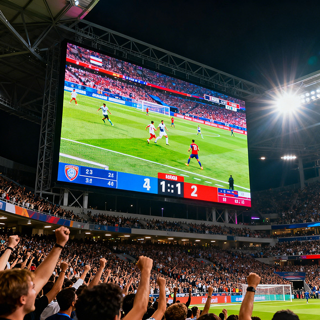
Overhead LED display · suspension, viewing distance and service access
Ceiling LED Screen
An overhead LED screen turns a ceiling into an active media surface. Its design starts with the host structure, suspension grid, installed load, viewing distance and a maintenance path. Those inputs determine the usable panel layout and whether the display should be flat, segmented or curved. It suits lobbies, casinos, retail atriums, museums and immersive venues where visitors experience content from below.
Send Drawing & Dimensions →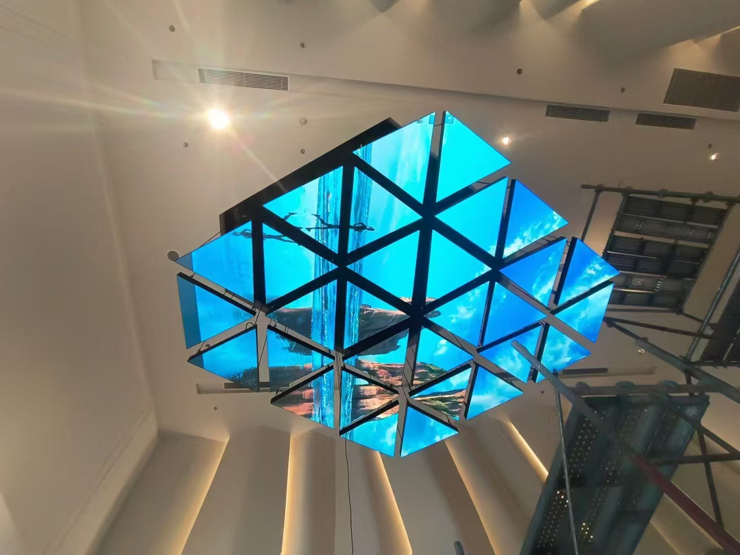
Definition
Plan the LED Ceiling, Building Structure and Audience Together
A ceiling display is not just a wall screen rotated upward. The active pixel plane, finished ceiling plane, support grid and service void must be coordinated with the building. Confirm how the modules attach to the host structure, how the installed load is carried, where fixtures and sprinklers remain clear, and how technicians will reach the equipment after the ceiling is finished.
For a continuous passage where the ceiling and sidewalls work together as one visual environment, compare Tunnel LED Display. A ceiling installation is designed around overhead suspension, structural load and viewing from below.
Engineering
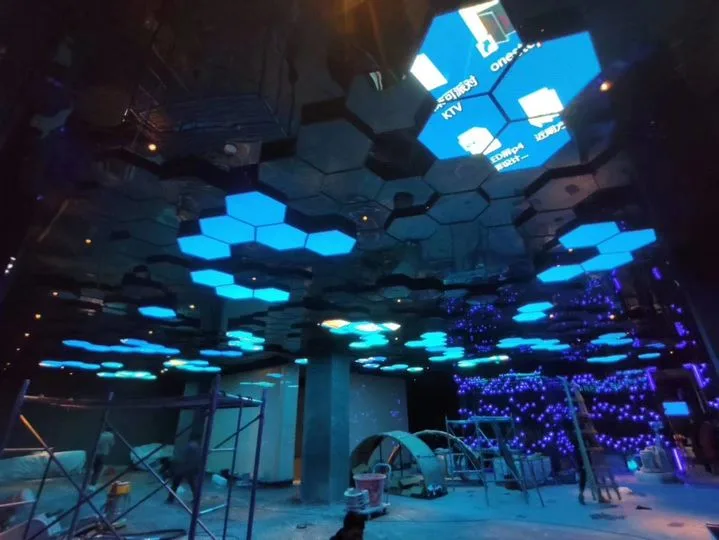
Engineering the Geometry of Ceiling LED Screen
Ceiling LED area
Set the active width and length separately from the trim, frame and service border. Record cut-outs for lights, sprinklers, sensors and architectural features so the pixel map follows the finished ceiling plan.
Finished ceiling elevation
Record the finished elevation and the actual vertical distance from the LED face to the occupied viewing area. This affects sightlines, perceived pixel detail and how motion or text should be designed.
Suspension-point grid
Dimension every hanger or attachment point from fixed building datums. Coordinate the grid with structural members and module joints; do not assume the ceiling substrate alone can carry the display.
Overhead dead load
Calculate the complete installed assembly, including panels, frames, cabling and suspension hardware. The building structure and its connections need review by the project’s qualified structural professional.
Service void depth
Reserve the space needed for power, data, ventilation and replacement access. Where the ceiling is enclosed, show access panels or a practical removal route before fabrication.
Viewer eye-to-ceiling distance
Use the real seating, circulation and standing positions to assess viewing distance and content legibility. Include the lowest clearance below the screen where people pass underneath.
Specification
Drawing Inputs Required for Overhead Led Ceiling
| Shape-specific engineering parameter | Value | Engineering use |
|---|---|---|
| Active LED area (width × length) | Project drawing; confirm dimensions on site | Separates the luminous pixel plane from framing, trim and architectural openings. |
| Finished LED face elevation | Project drawing; coordinate with ceiling datum | Establishes clearance below the display and the actual viewing distance from users. |
| Suspension / attachment-point grid | Set by module layout and verified with host structure | Locates each support in relation to building members, panel joints and installation sequence. |
| Complete installed dead load | Calculated for selected panels, frame and hardware | Provides the load basis for structural review and connection design. |
| Service void and access route | Project-specific; show access panels or removable zones | Keeps power, data, ventilation and component replacement reachable after installation. |
| Viewer-to-screen distance and clear height | Measured from occupied positions and circulation paths | Checks sightlines, content detail and safe head clearance below the screen. |
These are project coordination inputs, not fixed Highcolor product ratings. Confirm panel pitch, brightness, protection, weight and connection details for the selected system and venue.
Content & mapping
Map Content for Viewing from Below
The display map should follow the approved ceiling plan, not an assumed rectangular video canvas. Mark active modules, seams, cut-outs, inactive borders and orientation so the controller map matches the installed surface.
Review test content from representative audience positions. Large shapes and simple motion usually read more clearly overhead than dense small text; keep important content away from cuts, joints and fixture openings.
Installation decision
Coordinate Suspension, Safe Clearance and Maintenance Access
Start with the building’s structural grid and the specified attachment method. The installation drawing should show load paths, connection points, module sequence, edge finishing, cable routes and any secondary retention required by the project. Confirm the work-at-height and lifting plan with the site team.
Reserve a clear route for inspection and replacement before decorative ceilings or services close the void. If access is from above, coordinate walkways and removable panels; if service is from below, identify the lifting or removal method and protect the occupied area.
Cost drivers
What Drives the Cost of an Overhead LED Ceiling?
The estimate depends on the screen area and selected LED platform, but overhead work also adds structural coordination, lifting, site access and commissioning requirements. A reflected ceiling plan and section drawing help separate the display package from building work.
Screen Area & LED Platform
Active area, pixel pitch, brightness target and module format set the core hardware quantity and content capability.
Suspension & Structural Work
Attachment spacing, frame design, load review and any reinforcement can change fabrication and installation scope.
Site Access & Installation
Working height, lifting equipment, access windows, occupied spaces and service routes affect labor and project logistics.
Cut-outs, Edges & Commissioning
Light and sprinkler openings, edge finishing, cable routing, mapping and on-site calibration add project-specific work.
Drawing review
Review the Ceiling Plan, Sections and Support Details Before Production
Before release, check that the reflected ceiling plan, building structure and LED module layout describe the same installation. Resolve openings, support locations, access and viewing positions in the drawings rather than leaving them to site interpretation.
Ceiling LED area
Ceiling LED area is a shape-specific project input for Ceiling LED Screen. Put the confirmed value on the controlled drawing and use the same value for structure, segmentation, installation references and commissioning. The approved value should be shared by mechanical, control and content teams.
Finished ceiling elevation
Finished ceiling elevation is a shape-specific project input for Ceiling LED Screen. Put the confirmed value on the controlled drawing and use the same value for structure, segmentation, installation references and commissioning. Tolerance should be agreed where neighboring architecture or decorative finishes are already fixed.
Suspension-point grid
Suspension-point grid connects the LED assembly to the host structure. Its location should be coordinated with structural reactions, installation sequence and tolerances before production drawings are released. A site measurement and fabrication drawing should resolve any conflict before manufacturing.
Overhead dead load
Overhead dead load is needed for structural and handling decisions. Use the complete installed assembly rather than LED modules alone when checking supports, rigging, moving mechanisms or host-building capacity. This is one of the dimensions that should appear in the RFQ rather than being left to supplier interpretation.
Service void depth
Service void depth is a controlling envelope dimension for Ceiling LED Screen. Use the installed finished dimension and identify any trim, structural clearance or non-LED border separately so the active pixel area is not confused with the overall object size. Changing it late can affect several downstream parts, so revision control matters.
Viewer eye-to-ceiling distance
Viewer eye-to-ceiling distance is a shape-specific project input for Ceiling LED Screen. Put the confirmed value on the controlled drawing and use the same value for structure, segmentation, installation references and commissioning. For replacement or retrofit work, measure the existing condition instead of relying only on legacy drawings.
FAQ
Ceiling LED Screen Questions
What drawing is needed to quote Ceiling LED Screen?
Send a dimensioned sketch, CAD model or elevation showing ceiling led area, finished ceiling elevation and the active LED area. A reference image alone is not enough for final engineering.
Which geometry dimension controls Ceiling LED Screen most strongly?
Start with ceiling led area and finished ceiling elevation. The engineering team also needs suspension-point grid before module segmentation is frozen.
How should pixel mapping be prepared for Ceiling LED Screen?
Map the real active surface rather than forcing a standard 16:9 canvas. The controller map should follow the approved geometry, seams and inactive zones of this overhead LED ceiling project.
What service-access issue is specific to Ceiling LED Screen?
Access must be planned around viewer eye-to-ceiling distance. Components that become trapped behind the finished geometry should be identified before the support structure is released.
What usually changes the cost of Ceiling LED Screen?
The largest geometry-related variables are overhead area, suspension structure, safe service access and curved/segmented ceiling geometry. LED pitch and total active area also affect the final quotation.
Internal selection links
Compare Shapes With Different Engineering Intent
An led installation that turns across an inside or outside architectural corner while preserving image continuity.
An led surface engineered specifically around a 90-degree turn with controlled edge alignment.
A motorized led installation in which panels, tiles or objects move as part of the programmed visual composition.
Quote Ceiling LED Screen From the Drawing, Not the Name
Send the geometry, dimensions, viewing distance, indoor/outdoor condition, mounting interface, content concept and service-access requirement.
Request Engineering Review →