How to Install a Flexible LED Screen: Step-by-Step Guide
Installing a flexible LED screen is different from installing a conventional flat LED display.
The LED modules can bend, but that does not mean they can be attached directly to any curved surface. The final result depends heavily on the supporting structure, curve accuracy, module alignment, power and signal layout, and maintenance access.
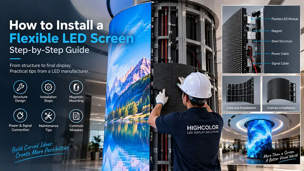
For cylindrical columns, curved retail displays and other creative LED installations, many visible problems actually begin behind the screen. An inaccurate steel structure, insufficient space for cables or an incorrect module layout can lead to uneven seams, distorted curves and difficult maintenance.
This guide explains how to install a flexible LED screen from a manufacturer’s perspective, including magnetic mounting, steel structures, concave and convex curves, wiring, maintenance and common installation mistakes.
How Is a Flexible LED Screen Installed?
A typical flexible LED display consists of flexible LED modules mounted onto a structure that defines the final shape of the screen.
For many indoor applications, magnetic mounting is used between the flexible modules and the supporting structure. This allows the modules to follow the designed curve while remaining removable from the front for service.
A typical installation sequence is:
Site measurement → curve calculation → supporting structure → power and signal layout → module installation → alignment → configuration → testing
The LED module provides flexibility, but the supporting structure determines the final geometry.
Flexible LED Screen Installation Structure
The following simplified diagram shows the basic relationship between the installation surface, supporting structure, magnetic mounting and flexible LED module.
| Layer | Function | Installation Requirement |
|---|---|---|
| Flexible LED Module | Creates the visible LED display surface | Must follow the permitted bending direction and radius |
| Magnetic Mounting | Secures the module while allowing front removal | Magnet positions need stable contact with the structure |
| Steel / Metal Structure | Defines the radius and overall screen geometry | Surface accuracy directly affects module alignment |
| Power & Signal Layer | Connects power supplies, receiving cards and modules | Needs planned cable routing and service access |
| Building / Decorative Surface | Supports the complete LED assembly | Must safely carry the installed load |
This is why the steel structure should not be treated as an afterthought. For a curved LED screen, it is part of the display system.
Step 1: Confirm the Screen Dimensions and Final Shape
Before fabricating the structure, confirm the actual display dimensions and geometry.
For a conventional curved wall, the project normally needs:
- screen width;
- screen height;
- curve direction;
- radius;
- concave or convex orientation; and
- installation position.
For a cylindrical LED screen, provide:
- column diameter or radius;
- display height;
- whether the LED covers 360° or only part of the circumference; and
- available installation depth.
For irregular shapes, architectural or CAD drawings are strongly recommended.
Do not manufacture the final supporting structure from an approximate radius if the LED modules have already been selected. The module dimensions and permitted bending range should be considered before the structure is finalized.
Step 2: Check the Flexible LED Module Bending Direction and Radius
Flexible LED modules are designed to bend in a specific way. They should not be treated like a sheet of fabric that can be twisted freely in every direction.
Before installation, confirm:
- module dimensions;
- permitted bending direction;
- minimum practical curve radius for the selected module;
- connector positions;
- magnet positions; and
- power and signal cable clearance.
Trying to force a module beyond its intended bending range can place unnecessary stress on the PCB, solder joints, connectors and electronic components.
The required curvature should therefore be discussed during product selection—not discovered after the steel structure has already been fabricated.
Step 3: Build an Accurate Supporting Structure
The supporting structure is one of the most important parts of curved LED screen installation.
A flexible module follows the surface behind it. If that surface is inaccurate, the LED face will also be inaccurate.
The structure needs to provide:
- the correct curve radius;
- consistent mounting points;
- sufficient rigidity;
- a smooth transition across structural sections;
- space for power supplies and receiving cards;
- cable routing; and
- maintenance access.
For magnetic installations, the contact surface also needs to be suitable for the module magnets.
Why Structure Accuracy Matters
Imagine a cylindrical display where one section of the frame is slightly farther outward than the next.
The flexible modules may still attach to the frame, but the LED surface can develop:
- visible steps between modules;
- uneven seams;
- local bulges;
- inconsistent curvature; and
- misaligned pixel rows.
These problems become particularly visible when the screen displays straight lines, grids or text.
Step 4: Plan Power Supplies and Receiving Cards Before Installing Modules
Do not cover the structure with LED modules first and then decide where the electronics should go.
The power and control architecture should be planned before module installation begins.
A typical system includes:
- AC power distribution;
- DC power supplies;
- receiving cards;
- power cables;
- signal cables;
- sending controller or media player; and
- video processor when required by the project.
The exact architecture depends on the screen resolution and application.
A small retail column running scheduled advertising content may use a different control configuration from a large curved stage screen receiving live HDMI or camera signals.
Keep Cable Length and Routing Under Control
Cables should be organized so they do not push against the rear of the flexible modules.
This is particularly important on small-radius curves where rear clearance can become limited.
A cable or connector trapped between the module and structure can prevent the magnets from seating correctly, creating a raised section on the display surface.
Step 5: Test the Modules Before Final Installation
Before installing every module onto the structure, power and test the modules according to the project configuration.
Check for:
- dead or abnormal pixels;
- incorrect color;
- signal problems;
- module-to-module brightness differences;
- connector issues; and
- physical damage.
Finding a faulty module before installation is much easier than troubleshooting it after a complete cylindrical or curved screen has been assembled.
Step 6: Install the Flexible LED Modules
Once the structure and internal electronics are ready, module installation can begin.
For a magnetic system, align the first module carefully before continuing across the screen.
The first row or reference line is important because small alignment errors can accumulate across a large curved surface.
A practical sequence is:
- Establish a horizontal or vertical reference line.
- Install the first module at the reference position.
- Check its level and curve alignment.
- Install the neighboring module.
- Check the seam before continuing.
- Connect power and signal according to the planned layout.
- Continue section by section rather than covering the entire structure immediately.
Do not use excessive force to make the module follow an incorrect frame.
If the module repeatedly lifts away from the structure or produces uneven seams, check the structure, magnet contact and cable clearance instead of forcing it into position.
Magnetic Installation for Flexible LED Modules
Magnetic mounting is commonly used because it makes flexible modules easier to position and remove from the front.
This is especially useful when the rear of the screen is difficult to access, such as:
- LED columns;
- retail feature walls;
- curved architectural displays;
- reception-area installations; and
- decorative indoor LED structures.
However, magnets do not eliminate the need for an accurate structure.
Each magnet needs proper contact with the mounting surface. If the supporting frame is uneven, the magnets may pull different parts of the module to different depths.
Concave vs. Convex LED Screen Installation
Concave and convex screens use similar flexible LED technology, but the mechanical conditions are different.
| Installation | Screen Shape | Key Installation Concern |
|---|---|---|
| Concave LED Screen | Curves inward toward the viewer | Maintain a consistent internal radius and avoid compression or uneven seams between modules |
| Convex LED Screen | Curves outward toward the viewer | Maintain consistent external curvature and reliable magnet contact across the frame |
| Cylindrical LED Screen | Continuous curve around a column | Circumference, final closing seam, cable routing and service access need to be planned together |
Pay Special Attention to the Closing Seam on a Cylinder
A 360-degree cylindrical screen introduces another challenge: the first and last modules eventually meet.
If the circumference calculation, structure diameter or module layout is incorrect, the final seam may be too wide, compressed or impossible to align properly.
For this reason, the relationship between:
module width × module quantity × final circumference
should be checked before the structure is manufactured.
Step 7: Check Module Seams and Surface Flatness
After each section is installed, inspect the display from different angles.
Look for:
- uneven module gaps;
- raised corners;
- modules sitting too deep;
- visible steps between modules;
- inconsistent curvature; and
- misaligned pixel rows.
Do this before the complete screen is finished.
Correcting a structural or alignment issue after dozens of modules have been installed usually requires much more work.
Step 8: Configure the LED Control System
After the hardware is connected, configure the LED control system according to the actual module and screen layout.
The configuration may include:
- screen pixel width and height;
- receiving-card mapping;
- module arrangement;
- signal direction;
- brightness settings;
- color calibration; and
- content source configuration.
For irregular or unusual screen layouts, signal mapping should be planned before installation so that the physical cable sequence matches the control configuration.
Step 9: Run a Full-Screen Test
Do not evaluate the completed screen using only promotional video.
Test patterns are much better for identifying installation problems.
Run:
- full red;
- full green;
- full blue;
- full white;
- grayscale;
- horizontal and vertical lines;
- grid patterns; and
- normal video content.
A grid or straight-line test is particularly useful on curved displays because it makes physical alignment errors easier to see.
How Much Maintenance Space Does a Flexible LED Screen Need?
This should be decided before installation.
Many flexible LED applications use front-access modules because there may be little or no usable space behind the display.
However, front-removable modules do not automatically mean that every component is easy to service.
You still need to consider access to:
- power supplies;
- receiving cards;
- power distribution;
- signal connections;
- cable joints; and
- structural fixing points.
For an architectural installation, determine how a technician will replace each major component before the decorative surface around the LED display is closed.
How Flexible LED Screen Thickness Affects Installation
Flexible LED displays are often selected where installation depth is limited, but module thickness is only one part of the total depth.
The complete installation depth includes:
LED module + magnets/mounting + structure + electronics + cable clearance + service space.
This is especially important on columns where increasing the installed depth also increases the final outside diameter.
For more detail, read our guide to flexible LED screen thickness.
Common Flexible LED Screen Installation Mistakes
| Common Mistake | Possible Result | Better Approach |
|---|---|---|
| Building the structure before confirming the module | Radius or dimensions may not match the module layout | Confirm module size and bending requirement first |
| Forcing the module into an excessive curve | Mechanical stress and unreliable installation | Stay within the selected module’s intended bending range |
| Uneven steel structure | Bulges, steps and uneven seams | Inspect structure radius and surface accuracy before mounting modules |
| No cable-routing plan | Cables can interfere with magnetic contact or servicing | Plan power and signal routes before module installation |
| No maintenance plan | Power supplies or receiving cards become difficult to replace | Design component access before closing the surrounding structure |
| Installing all modules before checking alignment | Small errors accumulate across the screen | Install and inspect section by section |
| Comparing only module dimensions | Electronics and structure may not fit available depth | Calculate the complete installed depth |
Flexible LED Screen Installation Checklist
Before installation starts, confirm the following:
- Final screen width and height
- Pixel pitch
- Module dimensions
- Concave, convex or cylindrical shape
- Curve radius or column diameter
- Module bending direction
- Supporting structure dimensions
- Magnetic mounting positions
- Power supply layout
- Receiving-card layout
- Power cable routing
- Signal cable routing
- Controller / processor configuration
- Front or rear maintenance method
- Replacement access for electronics
- Spare modules
- Full-screen testing procedure
For overseas projects, it is useful to complete as much system configuration and testing as possible before shipment.
Flexible LED Screen Installation FAQ
Can flexible LED modules be installed directly on a curved wall?
They need a suitable mounting surface and system design. The wall or supporting structure must provide the correct curve, reliable fixing points, space for electronics and a practical maintenance method. Do not assume that any existing curved wall is ready for direct LED module installation.
How are flexible LED modules fixed to the structure?
Magnetic mounting is commonly used for indoor flexible LED modules because it allows the modules to follow a metal structure and be removed from the front. The exact mounting method depends on the module and project design.
Can a flexible LED screen be installed as both concave and convex?
This depends on the design and permitted bending direction of the selected flexible module. Confirm the module specification before finalizing the supporting structure.
Can flexible LED modules make a 360-degree cylinder?
Yes, suitable flexible LED modules can be used for cylindrical displays. The module width, number of modules, column circumference, curve radius, closing seam and internal service space all need to be calculated together.
Does a flexible LED screen need a steel structure?
A supporting structure is generally required to define and maintain the screen geometry. The exact material and construction method depend on the installation and structural design.
How much space should be left behind a flexible LED screen?
There is no universal number. Required depth depends on the module, mounting system, power supplies, receiving cards, cable routing and maintenance method. Evaluate the complete assembly rather than module thickness alone.
Can flexible LED screens be front maintained?
Many flexible LED module systems use magnetic front access. However, the complete installation must also provide a way to access power supplies, receiving cards and other serviceable components.
Should the steel structure be made before ordering the LED modules?
For a custom curved project, it is safer to confirm the module dimensions, bending capability and layout before final fabrication of the supporting structure. Otherwise, the structure may not match the actual module geometry.
Plan the Flexible LED Screen Before Building the Structure
The most reliable flexible LED installations are usually planned as one complete system rather than as separate purchases of modules, steelwork and control equipment.
For a curved or cylindrical project, Highcolor recommends confirming the screen dimensions, pixel pitch, radius, module layout, supporting structure, power distribution, control system and maintenance method before production.
If your project already has an architectural drawing, CAD file or column dimensions, send them with your inquiry. This allows the LED layout and installation structure to be reviewed together.
Explore Highcolor Flexible LED Screen Solutions
Read: How Thick Are Flexible LED Screens?
Get Our Latest Products & News
Subscribe to our newsletter for fresh product launches, industry insights, and exclusive offers tailored for global partners. Stay ahead with updates that matter to your business!
Planning an LED display project?
Share a few details about your project and we’ll get back to you with a suitable solution and quote.