Lamp-Driver Separation in LED Displays: The Complete Technical Guide for Specifiers
What Is Lamp-Driver Separation?
In a conventional integrated LED module, the LED lamp beads (SMD or DIP) and the driver ICs (constant-current shift registers such as MBI5124, ICN2038S, etc.) are mounted on the same PCB—the so-called Lamp-Driver Integrated design.
Lamp-Driver Separation, sometimes described in datasheets as Separate Driver Board Design or Discrete Lamp & Driver PCB, physically splits the LED “light engine” onto one board (the Lamp Panel) and places the driver/receiver ICs on a separate board (the Driver Board or Hub Board), interconnecting them via short ribbon cables, pin headers, or FFC/FPC connectors.
This architectural split brings several lifecycle advantages.
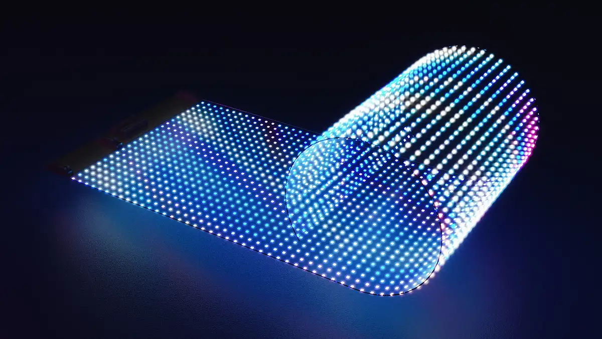
From a maintenance perspective, a failed lamp panel can be swapped without discarding driver electronics, and vice versa—reducing e-waste and spare-part cost over a 5–7 year lifecycle.
Thermally, moving the driver IC’s heat load away from the LED junction zone reduces operating temperature and slows lumen depreciation.
Electrically, the driver board can be positioned in a ventilated area or even centralized in a rack, simplifying large-format cabinet thermal design.
Separation introduces additional interconnects (a potential EMI and signal integrity concern if poorly executed), requires careful cable length management to avoid voltage drop on the cathode/anode feeds, and increases initial harnessing complexity.
However, for fine-pitch indoor walls, 24/7 control rooms, and large outdoor signage where serviceability and thermal headroom matter, the Total Cost of Ownership (TCO) usually favors separation despite slightly higher initial labor.
Thermal Management and Heat Dissipation Advantages
Driver ICs in medium-to-large LED displays can dissipate 0.5 W–1.5 W each under full load, and a high-density module may host 16–32 driver ICs.
In an integrated design, this heat is concentrated immediately behind the LED array, raising the local PCB temperature and, by conduction, the LED junction temperature (Tj).
Elevated Tj accelerates phosphor degradation in SMD LEDs and shifts wavelength characteristics—resulting in visible color drift over time.
Lamp-Driver Separation physically relocates this heat source.
The Lamp Panel contains only passive components and LEDs; the Driver Board is mounted on the rear of the cabinet or in a dedicated compartment with its own airflow path. In side-by-side thermal chamber tests we have observed:
- Ambient + Loaded Temp on Integrated Module (P2.5, 4500 nits): LED area ≈ +28 °C above ambient
- Same Pitch, Lamp-Driver Separated, rear-exhaust fan: LED area ≈ +14 °C above ambient
This ~14 °C reduction in LED-zone temperature can extend LED useful life by 30–40% per the Arrhenius rule commonly applied in solid-state lighting.
Lower Tj also stabilizes chromaticity—important in broadcast and color-critical control room environments.
Best practice thermal design for separated drivers includes: aluminum-back rear trays for the driver board, vertical chimney-style airflow in tall cabinets, and avoiding dense driver clustering without local heatsinking.
Some manufacturers pair lamp-driver separation with Common-Cathode (Constant Voltage) driving to further reduce I²R heating on the LED side.
Wiring Distance, Voltage Drop, and Electrical Performance
When the driver board is physically separated from the lamp panel, typically 50 mm to 300 mm inside a cabinet, but occasionally up to 1–2 m in distributed architectures, two electrical concerns arise: voltage drop on power feed lines and signal integrity on scan/data lines.
Voltage Drop:
The LED rows/columns are fed from the driver board’s output pins through multi-conductor flat cables. Copper resistance causes a voltage drop (ΔV = I × R).
For a red LED row drawing 2 A through a 0.1 Ω harness, ΔV ≈ 0.2 V—enough to cause visible brightness non-uniformity between the near and far ends of a wide module if the cable is undersized.
Mitigation strategies include using wider/parallel conductors in the FFC, locating the driver board centrally relative to multiple lamp panels, and selecting driver ICs with built-in pre-charge / grayscale compensation.
Signal Integrity:
Clock and data lines (typically 10–30 MHz serial shift clocks) are short-distance TTL/CMOS signals.
Beyond ~300 mm, crosstalk and ringing can occur. Premium implementations use differential signaling for the high-speed control bus or buffer/repeat the signal on the driver board before distribution.
Proper grounding—dedicated return paths in the ribbon and star-grounding the driver board to the main power supply is essential to suppress EMI, especially in U.S. installations subject to FCC Part 15 Class A limits.
From a code perspective, low-voltage Class 2 wiring (typically ≤60 V DC) feeding the lamp panels must comply with NEC Article 725 for power-limited circuits—proper separation from AC mains, use of listed cables, and appropriate overcurrent protection on the central power supplies.
Driver Types, Scan Modes, and Code-Compliant Installation
Lamp-driver separation is compatible with all common LED driver IC topologies: constant-current (CC) drivers for precise mA regulation across temperature, and constant-voltage setups with external current-limiting resistors (less common in fine pitch).
Scan modes—1/8, 1/16, 1/32, etc.—are configured via the driver IC and matching resistor networks on the lamp panel; the separation itself does not change scan ratio but makes it easier to swap driver boards if you change scan strategy.
For U.S. commercial installations, the following installation practices are recommended:
Grounding & Bonding:
The driver board’s ground plane must be bonded to the metal cabinet and ultimately to the building’s signal ground or isolated earth per NEC Article 250.
Floating grounds between lamp and driver boards cause ghosting images and increase ESD risk.
Surge Protection:
Centralized driver boards should be fed from switched-mode power supplies with built-in surge suppression (≥ 2 kV line-to-line per UL 60950-1 / UL 62368-1 transition guidance).
Where the driver is mounted separately from the LED cabinet (e.g., in a rack room feeding façade signage), consider an external TVSS on the DC feeders.
Fire &> Spacing:
Ensure driver boards are mounted with adequate clearance from combustible backing materials and that wireways are sized per NEC fill tables. Avoid bundling high-current LED power feeds tightly with low-voltage data ribbons—this is a frequent installer error that manifests as intermittent flicker.
Incorrect orientation of the FFC connector (reversed pinout) and missing jumper settings for scan mode are the two most common field mistakes with separated-driver retrofits. Clearly labeled pin-1 indicators and color-coded harnesses should be specified.
Impact on Display Performance: Color Uniformity, Brightness, and Refresh Rates
A well-executed lamp-driver separation design can improve perceived image quality, though the architecture itself is secondary to the quality of the driver IC and calibration process.
By removing driver IC heat from the lamp zone, the LED junction temperature stays more consistent across the screen surface, reducing thermally induced wavelength shift—particularly beneficial for red LEDs, which are most temperature-sensitive.
Brightness uniformity benefits indirectly: because voltage drop can be better managed on a purpose-designed driver board (with localized sensing or programmable output current per channel), the gamma-corrected grayscale remains linear across the panel.
High-refresh-rate performance (≥3840 Hz, required for broadcast/camera use) is unchanged by separation per se, but the ability to place higher-performance driver ICs on a better-cooled board allows sustained operation at high PWM frequencies without thermal throttling, something integrated modules sometimes struggle with in enclosed cabinets.
Compared to newer packaging approaches, COB (Chip-on-Board) and GOB (Glue-On-Board) primarily address surface protection and pixel pitch miniaturization; they do not replace the lamp-driver separation concept.
High-end COB modules are frequently paired with separated drivers for exactly the same thermal and serviceability reasons discussed here.
Get a Lamp-Driver Separation Solution Engineered for Your Project
Whether you are specifying a new fine-pitch indoor wall, retrofitting an existing sign, or designing a custom control-room visualization system, our engineering team can assist with driver-board layout review, thermal simulation, and NEC-compliant wiring diagrams.
Contact us today to request a free LED display specification worksheet and TCO comparison between integrated and separated driver architectures for your exact screen size and operating hours.
We support turnkey supply and certified installation partners throughout the United States.
Preguntas frecuentes
What’s the difference between lamp-driver integration and lamp-driver separation in LED displays?
In integrated designs, LED lamps and driver ICs share one PCB; in separated designs, LEDs are on a dedicated lamp panel and driver ICs are on a separate driver board connected by cables or FFC. Separation improves thermal management, serviceability, and long-term reliability but requires careful wiring and signal design.
What does an LED driver do in a lamp-driver separation setup?
The driver ICs on the separate board control the current sunk or sourced through each LED row/column, latch grayscale data from the receiving card, and regulate timing. They perform the same function as in integrated modules but are physically decoupled from the LED array.
How does lamp-driver separation affect LED lifespan and heat management?
By moving driver IC heat away from the LED zone, junction temperature is lowered—typically by 10–15 °C in well-designed cabinets—which can extend LED life by 30%+ and reduce color shift over time.
How far can you separate the driver from the LED lamp without performance loss?
Inside a cabinet, 50–300 mm is typical with standard FFC. Up to 1–2 m is possible with properly sized conductors, buffered signals, and voltage-drop compensation. Beyond that, signal integrity and IR drop usually require a distributed drive approach instead.
What are the best practices for centrally organizing LED drivers?
Use star grounding, individually fused DC feeds per driver board, adequate ventilation or active cooling for the driver enclosure, and clearly labeled, keyed connectors to prevent miswiring. Keep data and power conductors separated per good EMI practice.
Does lamp-driver separation support dimming and smart driver controls?
Yes. Most modern constant-current driver ICs support global/individual brightness adjustment via the control system (often over Ethernet-based protocols such as NovaStar, Colorlight, or Brompton). Separation does not limit dimming capability.
Can I retrofit an existing LED screen to use lamp-driver separation?
Only if the original module was designed for it or you are replacing both lamp panels and driver boards with a matched set. True retrofitting of an integrated module to separated architecture is generally not feasible; however, upgrading an older integrated cabinet system to a new separated-driver module family is common and recommended for long-term serviceability.
Entérate de nuestros últimos productos y novedades
Suscríbete a nuestro boletín para recibir información sobre nuevos lanzamientos de productos, análisis del sector y ofertas exclusivas diseñadas para socios de todo el mundo. ¡Mantente a la vanguardia con las novedades que importan para tu negocio!